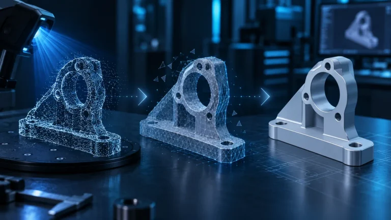
Scan → STL → slicer → print can work extremely well when the goal is to reproduce the measured surface. Functional replacement parts are a different case.
Five checks before the slicer
- Verify scale and one known dimension.
- Repair unintended open boundaries.
- Check normals.
- Evaluate wall thickness.
- Remove islands and self-intersections.
Why scan meshes are often too heavy
A scan may contain millions of points. A 0.4 mm FDM nozzle cannot reproduce unlimited surface frequency, so controlled decimation can reduce slicer load without visible loss.
Units and scale
STL does not inherently define a physical unit. A mismatch can introduce factors such as 25.4 or 1000. Measure a known feature in the slicer.
Wall thickness is not automatic
Scanners capture surfaces. Thin sheet parts can produce open or inconsistent meshes unless both sides are captured and connected correctly.
Choose print orientation again
Scan orientation is not print orientation. Overhangs, support, layer strength, stair-stepping and bed contact still matter.
When direct scan-to-print works well
- figurines and sculptures
- ergonomic shapes
- fit mockups without precision mechanics
- historic/organic surfaces
- objects where the measured surface is the desired result
When CAD is better
- bolted interfaces
- bearing/sealing seats
- clips and snap fits
- planar mounting surfaces
- parts requiring later parametric changes
FDM or resin?
Resin can reproduce finer surface detail; FDM is often practical for larger functional parts. Match scan density to the actual output process instead of maximizing polygon count.
Mesh errors slicers may hide
Modern slicers repair small defects automatically. That convenience can hide unwanted changes: an opening may be closed or a thin wall may disappear. Critical scan meshes should be checked before slicing.
Secure scale with a real reference dimension
Use a feature that is easy to measure on the original, such as hole spacing or overall width. Verify that exact dimension after import. On large parts, use several references far apart to reveal global distortion.
Create thickness for open scans
A one-sided scan may be only a mathematical skin. Organic models can often use shell/solidify tools; technical parts are usually better controlled in CAD.
Match mesh resolution to the printer
High-resolution resin can preserve more scan detail than a large FDM prototype. Feeding a 50-million-triangle mesh to an FDM slicer is pointless if line width and layer height cannot reproduce the surface frequency.
Functional fits still need design tolerance
A scanned clip represents the original geometry, not the process compensation needed for your printer and material. Shrinkage, anisotropy and printer tolerance may require deliberate clearance changes.
Direct scan-to-print excels on organic forms
Sculptures, body forms, ergonomic grips and historic surfaces often benefit from staying as meshes. Parametric reconstruction would add work and may remove characteristic detail.
Print a fit sample first
For a large scanned part, cut out a small interface or contact region and print that as a test. It is much cheaper than discovering a scale or fit problem after a multi-hour full-size print.
Start by deciding whether you are copying a surface or reconstructing a function
For a sculpture, handle or organic shape, the measured surface may be exactly what you want. For an engineered replacement part with screws, bearings or clips, it is only the starting point. Make that decision before aggressive mesh repair because it determines which holes may be filled and which geometry should move to CAD.
Put Creality’s direct scan-to-print workflow in context
The current Creality Wiki documents a straightforward route through fusion, meshing, watertight/hole filling, STL export and slicing. It is a strong default for organic and decorative objects. For this path Creality commonly recommends around 0.2 to 1 million mesh triangles—enough detail without needless slicer load.
For engineered parts, however, an automatically closed opening may have been a real functional feature. Critical geometry must be reviewed before using one-click watertight processing.
Check at least two reference dimensions
Verify one local feature such as a hole spacing and one large overall dimension after export. This catches both unit/scale errors and broader drift. Long parts may justify additional references on multiple axes.
Turn scanned surfaces into printable walls deliberately
A scanned surface has no guaranteed manufacturing wall thickness. Covers and trim pieces may require an inner surface captured separately, reconstructed in CAD or generated with a shell/solidify operation. A uniform offset can create interference on tight-fitting parts.
FDM-specific adjustments
- Reconsider layer orientation and load direction.
- Calibrate holes and clips rather than blindly reproducing mesh dimensions.
- Choose support from print geometry, not scan orientation.
- Discard surface frequencies below realistic line-width/layer capability.
- Reduce excessive mesh density before slicing large projects.
Resin-specific adjustments
Resin can reproduce finer surface detail, but hollowing, drain holes, suction forces and support contact become important. A watertight scan is not automatically a good resin-print model.
Print a fit sample before the full object
For a 300-mm replacement part, printing only the mounting interface or clip region is usually more efficient than committing to the full model. Validate holes, clips and mating contours first.
A practical end-to-end workflow
- Inspect the scan for coverage and tracking errors.
- Fuse at a resolution appropriate to object size.
- Create only as much mesh density as needed.
- Review critical holes and open regions manually.
- Check scale against real references.
- Move functional geometry to CAD when appropriate.
- Re-decide orientation, tolerance and material.
- Print critical interfaces as a partial test.
- Only then manufacture the full model.
Watertight is often required by slicers, but it is not proof of accuracy
Creality recommends closing openings for direct printing so the slicer can interpret a clear solid volume. That is technically useful, but an automatically reconstructed patch can still be geometrically wrong. Critical functional areas must be reviewed before accepting the repair.
Match scan resolution to real print resolution
A scanner can record details that a 0.4-mm FDM process cannot reproduce, while resin may benefit from finer surface data. Final mesh density should therefore match nozzle, layer height, model size and output goal rather than staying maximized for its own sake.
Use a reference dimension through the complete pipeline
Keep at least one known dimension in the project and verify it after fusion, mesh export and slicer import. This helps isolate whether a scale or geometry error was introduced during capture, processing or file import.
Conclusion
Direct scan-to-print is strongest when the mesh itself is the deliverable. When nominal dimensions and editability matter, use the scan as CAD reference.
Sources & current status
- Creality Wiki
- Creality Wiki
- Creality Wiki – 3D Scanner Support Center
- Payo / Tensile Creator – practical 3D scanning & reverse engineering
- Autodesk – Scan to CAD workflow
- Creality CR-Scan Otter – official product data
Updated August 2026.
Frequently asked questions
Can every scanner STL be sliced directly?
No. Open boundaries, self-intersections, scale errors and thin areas can cause problems.
Do I need to smooth a scan?
Not necessarily. Mild scan noise may be less harmful than heavy smoothing that removes detail and dimensions.
When is CAD better?
When fits, bores, clips, planar interfaces or future parametric changes matter.