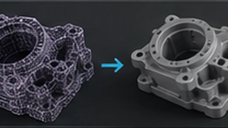
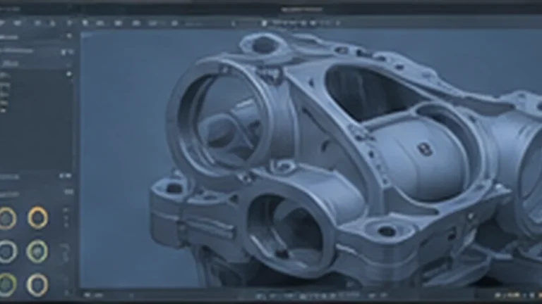
A 3D scanner does not initially give you a “real CAD file.” It produces measurement data and usually a triangulated mesh. That mesh may already be enough for 3D printing. But once you want to change holes, define exact mating faces, control dimensions or develop a technical replacement part further, you usually need another step: use the scan as a reference and reconstruct the part as CAD geometry.
This is the key difference between simply “converting STL to STEP” and actual reverse engineering. Automatic conversion can create a solid, but it does not automatically create a clean, parametric and easy-to-edit model.

Why a scan is not automatically CAD
A scan mesh consists of many triangles. Those triangles describe a surface, but they do not know that a region was intended to be perfectly planar, a hole truly cylindrical or two faces exactly perpendicular. CAD models instead use geometric entities such as planes, cylinders, sketches, extrusions, fillets and controlled dimensions.
| Scan mesh | CAD / B-Rep / STEP |
|---|---|
| many triangular faces | analytic or NURBS surfaces |
| excellent as a shape reference | better for dimensioning and editing |
| may contain noise and measurement error | construction geometry can be idealized |
| a hole is just faceted surface data | a hole can be rebuilt as a true cylinder/feature |
| local edits can be awkward | dimensions and features can be changed deliberately |
The common mistake: simply converting STL to a solid
Fusion can convert a mesh directly to a solid or surface body. Autodesk provides methods including Faceted and Prismatic. This can be useful, but direct conversion is not the same as rebuilding clean CAD.
A faceted conversion can preserve essentially every triangle as a separate B-Rep face. The result is formally a solid, yet still painful to edit. On simple manufactured geometry, prismatic recognition can work better because related regions may be interpreted as planar or cylindrical features.
When direct mesh conversion can still make sense
- a small, clean mesh with a modest facet count,
- simple manufactured geometry,
- you mainly need a solid for a downstream operation,
- few design changes are planned,
- the mesh is closed and already repaired.
Autodesk explicitly warns that large meshes can make conversion slow or fail. Current Fusion guidance notes that direct conversion is considerably more practical below roughly 10,000 facets. A detailed scan can easily contain hundreds of thousands or millions of triangles.
Step 1: prepare the scan and mesh first
Before CAD work starts, the reference itself has to be trustworthy. Reverse engineering cannot magically turn a poor scan into accurate geometry.
- Remove outliers: delete floating points and unrelated geometry.
- Evaluate holes carefully: do not blindly fill openings that are actual design features.
- Reduce noise: without smoothing away important edges.
- Check units: confirm millimeters vs inches.
- Verify a reference dimension: cross-check at least one real measurement with calipers or a micrometer.
- Align the coordinate system: place major reference faces sensibly on XY/XZ/YZ.
For the cleanup stage, see 3D Scan: Point Cloud to Clean Mesh. The broader workflow is covered in our 3D Scan → CAD / Reverse Engineering pillar.
Step 2: identify design intent instead of tracing everything
Before modeling a technical part, ask how the original part was probably designed. Many seemingly complex scan meshes reduce to a handful of basic features:
- a base plate,
- one or more extruded profiles,
- cylindrical holes,
- symmetry,
- ribs or gussets,
- fillets and chamfers.
The scan becomes a measurement body that these idealized elements are fitted to. This is what makes the final CAD model easier to modify than the noisy source mesh.
Step 3: use mesh section sketches instead of freehand tracing
Fusion has a particularly useful reverse-engineering tool: Create Mesh Section Sketch. A plane intersects the mesh and produces a section reference. Fit Curves To Mesh Section can then fit lines, arcs or splines to that section.
This is often much more controlled than picking arbitrary 3D points. Multiple sections can be used as profiles for extrusions, lofts or sweeps.
| Geometry | Typical CAD rebuild |
|---|---|
| base plate | plane + 2D sketch + extrusion |
| round hole | determine center + true circle/cylinder |
| symmetric bracket | rebuild one side + mirror |
| organic profile | several sections + loft/spline |
| rib/gusset | sketch line + rib/extrusion |
| fillet | build primary geometry first, add radius late |
Step 4: idealize holes and mating faces
For functional replacement parts, do not automatically use every noisy scan dimension literally. An original 10 mm hole may appear as 9.91–10.08 mm in a mesh depending on scanner resolution, surface condition and alignment.
Combine scan data with conventional measurement:
- derive position and axis from the scan,
- measure the actual diameter separately,
- determine a plausible nominal dimension,
- rebuild it as a true circle/cylinder in CAD.
Printing introduces another layer of tolerance. Our Dimensional Accuracy & Shrinkage analysis helps keep scan/CAD accuracy separate from the dimensional behavior of the final FDM print.
Step 5: compare the CAD model against the scan
Keep the source mesh visible after rebuilding the CAD geometry. This lets you check where the idealized model deviates from the measured surface.
Not every deviation is bad. A useful reverse-engineering workflow distinguishes:
- intentional idealization: a plane replacing scan noise,
- manufacturing or wear: a warped or worn original part,
- a true modeling error: a reconstructed axis, distance or angle is wrong.
For replacement parts, reproducing the original wear can actually be the wrong goal.
Reduce the mesh: fewer triangles without losing the truth
If Fusion becomes slow, mesh reduction is often necessary. The goal is not simply to delete as many triangles as possible. Critical edges, holes and functional transitions must remain reliable.
- keep only the scan region relevant to the part,
- reduce large planar regions more aggressively,
- preserve edges and small functional features more carefully,
- compare reference dimensions before and after reduction.
When STEP is actually the right output
STEP is useful when the reconstructed part needs to move between CAD systems as geometric data. But STEP is not automatically parametric: it can transfer clean B-Rep geometry without preserving the full feature history of the original CAD file.
- STL/3MF: ideal for slicers and printing, poor for comfortable technical redesign.
- STEP: excellent for exchanging clean CAD bodies.
- native CAD file: best when feature history and parameters need to remain editable.
When automated surface reconstruction is the better tool
For complex freeform parts, castings, body panels or organic geometry, manual parametric reconstruction can become very time-consuming. Specialized scan-to-CAD/reverse-engineering software can then be worthwhile because it can derive surfaces and features more automatically.
For typical 3D-printed replacement parts, brackets, housings and technical components, deliberate parametric rebuilding is often simpler and easier to edit later.
Practical example: a scanned bracket
- Scan the part and align the mesh.
- Identify the base plane.
- Reconstruct the outer profile from a mesh section.
- Rebuild mounting holes as true circles using verified nominal dimensions.
- Extrude the upright bracket.
- Reconstruct the large bearing/through-hole on its own axis.
- Add ribs/gussets.
- Add fillets/chamfers last.
- Overlay CAD and mesh to check deviation.
- Save the native CAD file and export STEP; export STL/3MF separately for printing.
Common Scan → STEP mistakes
| Mistake | Why it hurts | Better approach |
|---|---|---|
| converting a multi-million-triangle mesh directly | slow, unstable and difficult to edit | reduce the relevant region and rebuild parametrically |
| reproducing every scan ripple | noise becomes CAD geometry | use plausible planes, axes and nominal dimensions |
| trusting scan dimensions only | sensor error and wear get copied | verify critical dimensions physically |
| adding fillets first | makes primary geometry unnecessarily complex | build the base form first, fillets/chamfers later |
| assuming STEP means parametric | feature history may be gone | keep the native CAD file too |
Conclusion
A strong scan-to-CAD workflow does not try to preserve every triangle. It uses the scan as a precise reference for location, form and proportion, then rebuilds the part as technically meaningful CAD geometry.
For functional parts, mesh → sections/references → parametric rebuild → validation → STEP is usually far more useful than a quick STL-to-solid conversion. The final model is easier to edit, dimension, repair and reuse for future variants.
Sources & current status
- Autodesk Fusion – Convert a mesh body to a solid body
- Autodesk Fusion – Create Mesh Section Sketch
- Autodesk Fusion – Fit Curves to Mesh Sections
- Autodesk – Mesh to B-Rep / solid conversion and mesh complexity guidance
Research status: September 7, 2026. Menu names and functionality can change with Fusion updates.
Frequently asked questions
Can I simply save a 3D scan mesh as STEP?
Some CAD tools can convert meshes directly into solid/surface geometry. For a clean editable technical model, rebuilding the design parametrically from the scan is often much more useful.
Why is a directly converted STL often difficult to edit?
A faceted conversion can retain huge numbers of individual faces. The result may technically be a solid but remain nearly as cumbersome as the original mesh.
What are Mesh Section Sketches used for in Fusion?
They create section references through a mesh. Lines, arcs and splines can then be fitted to those sections and used to rebuild parametric sketches and CAD bodies.
Should I trust every dimension from the scan?
No. Critical holes, distances and mating features should also be measured physically. Scan noise, wear and surface issues can otherwise become incorrect CAD dimensions.
Is STEP always parametrically editable?
STEP can transfer clean CAD geometry, but it does not necessarily preserve the full feature history or parametric structure of the source model. Keep the native CAD file as well.