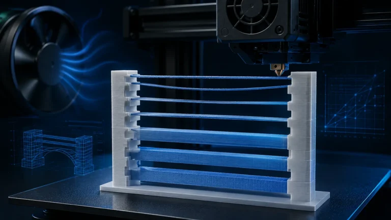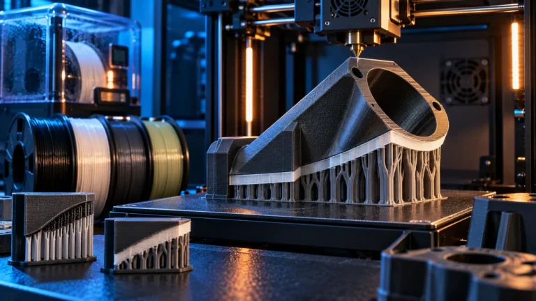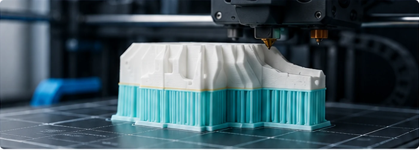
PLA and PETG generally do not bond strongly to each other. That weakness can be useful: print the model in one polymer and use the other only for the dense support interface. The interface can sit very close to the model for better underside quality and still separate after printing.
The trick is powerful, but it is not “set PETG as support and forget it.” Interface thickness, Z gap, cooling, purge contamination and the printer’s multi-material architecture all matter.
Why PLA and PETG can work as a separation layer
The polymers have different chemistry and typically form a weaker bond to each other than to themselves. That means the support can contact the model more closely without fusing as strongly as same-material support.
This is a practical effect, not a guarantee. Additives, colors, temperatures and contamination can change the bond. Always verify the exact material pair with a small test.
Interface instead of the entire support: the biggest saving
Printing all support in the second material creates many more material changes and may add a large purge penalty. In most cases, the useful separation happens only at the contact surface. Keep the main support structure in the model material and assign the second polymer only to the support interface layers.
An OrcaSlicer detail: the transition/bonding layer
When a separate interface filament is selected, multiple interface layers do not always mean every one of those layers is printed entirely in the second material. Slicer logic can include a base or transition layer to stabilize the interface. That affects both the number of material changes and how the support behaves mechanically.
PLA model with PETG interface
This is a common combination for flat ceilings and difficult undersides. PETG can provide a dense support surface beneath PLA while remaining comparatively easy to separate.
Advantages
- Very small Z gap can be possible.
- Flat supported surfaces can become much cleaner.
- The second material is only needed in a few layers.
What to watch
- PETG strings easily when wet.
- Too much contamination with PLA can change separation.
- High PETG temperature can leave a rough interface if cooling is insufficient.
PETG model with PLA interface
The reverse combination can work as well. PLA usually cools faster and may produce a crisp interface, but temperature transitions are larger. Toolchangers handle that comfortably because each material stays in its own hotend; single-nozzle systems must fully exchange the melt path.
Top Z Distance: 0 mm is possible, but not a rule
Because the polymers themselves provide the separation, a zero Z gap can produce an underside that looks almost like a normal printed surface. But zero is not automatically best. If the interface welds too strongly, the supported surface is rough or the support damages the model, test a small positive gap.
One, two or three interface layers?
More dense layers make the interface more stable and can support bridges better, but they also increase print time and may create additional material changes. Start with a small number and increase only when the supported surface needs more stiffness.
| Interface setup | Advantage | Tradeoff |
|---|---|---|
| 1 dense layer | Fewest material changes | Less tolerant of uneven support geometry |
| 2 layers | More stable support roof | More time and one or more additional transitions |
| 3+ layers | Can create a very uniform interface | Often unnecessary; increases material and change count |
Choose enough interface thickness for a stable roof; judge underside quality and removal together.
Interface spacing and pattern
A denser interface supports the model more evenly but costs more material and can increase separation force. Rectilinear patterns are a good baseline; concentric or other patterns may suit curved geometry. The correct spacing depends on nozzle size, layer height and the surface you are trying to support.
Cooling the support interface
Higher interface cooling can reduce bonding and help the supported polymer solidify before the next layer. That is useful when the model material tolerates the cooling. Avoid treating interface cooling as an isolated setting; strong fan changes can also affect warping or layer adhesion elsewhere.
Do not forget Support/Object XY Distance
A perfect top interface does not help if the support is fused to the model’s vertical sides. XY distance controls lateral separation. Tune it independently from the top Z gap, especially around holes, letters and narrow channels.
Toolchanger: the ideal use case
Separate nozzles keep PLA and PETG in separate melt zones, so there is far less cross-contamination. The main challenges are parked-tool ooze, standby temperature, priming and tool-offset accuracy. If those are well controlled, interface-material support can be fast and clean.
Single nozzle with AMS/MMU: it works, but costs more
When both polymers share one hotend, every interface transition requires a melt-path exchange. That means more purge, more time and more opportunities for contamination. The technique is still useful, but the economics are very different from a toolchanger.
Color that looks clean does not establish polymer purity. Evaluate interface separation and model integrity; keep the final contact layers as compositionally clean as practical.
Why “flush into support” needs caution here
Normally it is clever to hide purge inside support. But when support separation depends on a clean PLA/PETG boundary, flushing the wrong material into the interface can undermine the whole purpose. Use flush-into-support only where contamination cannot reach the critical contact layers.
Prime/wipe tower with mixed materials
A tower can help stabilize pressure and keep the nozzle cleaner after changes. Do not judge the purge requirement only by color purity. For a separation interface, polymer purity at the boundary matters too.
Starting profile for a new PLA/PETG test
- Use the second material only for the interface.
- Start with 1–2 dense interface layers.
- Use a conservative, low Z gap and adjust from the result.
- Keep interface lines dense enough to support the model.
- Use adequate interface cooling if both materials tolerate it.
- Use safe purge values for polymer changes.
- Test on a small repeatable object first.
The best calibration object is not a Benchy
Use a model with a flat supported ceiling, a curved underside and one narrow supported feature. That lets you evaluate removal force, underside finish, side clearance and purge contamination in one short print.
Typical problems and likely causes
| Problem | Likely cause | First adjustment |
|---|---|---|
| Support fuses too strongly | Too much contamination, too much heat or zero gap too aggressive | Increase purge quality or add a small Z gap |
| Underside sags | Interface too sparse or not stiff enough | Add interface density/layers |
| Support collapses | Main support structure too weak | Strengthen base support, not only interface |
| Too many material changes | Second material used for all support | Assign it only to the interface |
| Interface strings badly | Wet PETG or temperature/retraction issue | Dry filament before tuning retraction |
| Support edge scars the wall | Lateral gap too small | Inspect Support/Object XY Distance separately from the top gap |
| First path after a swap is missing | Restart priming or tool-change sequence | Inspect restart and tower behavior before changing the interface gap |
When PLA/PETG is not the best solution
For very high-temperature polymers, chemically incompatible environments or prints where even tiny contamination is unacceptable, dedicated soluble or breakaway support may be better. Very small parts can also lose more time to changes than they gain in removal quality.
PLA/PETG vs. dedicated support filament
Dedicated support materials can offer easier separation or solubility, but they are usually more expensive and may require drying or special storage. PLA/PETG is attractive because both materials are common and inexpensive. The best choice depends on the geometry and the value of your time.
Conclusion
PLA/PETG support interfaces work best when you treat them as a controlled material boundary, not simply as a different support color. Keep the second material in the interface, protect that boundary from contamination and tune Z gap, cooling and interface density together.