Ironing is one of those slicer features that can transform a top surface with a single checkbox — and still disappoint when the default values do not match the print. The principle is simple: after the normal top skin is printed, the hot nozzle travels over the same Z height again, extruding only a very small amount of material. It presses down small high spots and adds enough polymer to fill shallow valleys.
In practice, several coupled settings decide whether the result becomes genuinely smooth or develops grooves, dragged plastic, fuzzy edges and alternating matte/gloss bands. That is why a slicer’s stock values are not necessarily “wrong”, but they are also not a fully calibrated ironing profile for every printer, nozzle, layer height and filament combination. Current Bambu Studio base process profiles, for example, include 10% ironing flow, 0.15 mm spacing and 30 mm/s, while Prusa profile families use other combinations. These values are starting points, not universal physical constants.
What ironing actually does
Ironing does not print another normal top layer. The nozzle stays at the same layer height and makes a second pass. Two effects happen at once:
- mechanical smoothing: the hot nozzle face flattens small raised areas,
- micro-extrusion: a low flow fills shallow gaps between existing top-surface lines.
This makes ironing closer to “smoothing plus controlled filling” than sanding. It also explains why flow and line spacing must be tuned together. Tight spacing makes the nozzle revisit the same surface area more often. If flow is also too high, plastic can accumulate ahead of the nozzle and be pushed across the surface.
OrcaSlicer documents the same trade-off: lower flow can produce a smoother finish but may fail to cover the surface fully, while higher flow can improve coverage yet cause over-extrusion or a rougher result.
Why default values behave differently from one printer to another
An ironing preset cannot automatically know the real condition of your top skin. Two prints using the same 0.4-mm nozzle and the same slicer can react differently if only one of these variables changes:
- actual filament flow and Flow Ratio calibration,
- top-surface line width,
- layer height,
- top-shell count and total top thickness,
- top-surface pattern and direction,
- temperature and cooling,
- material formulation — even within “PLA”,
- size and geometry of the ironed islands,
- nozzle shape, wear or contamination.
This is why copy-paste claims such as “15% flow at 30 mm/s is perfect” cannot be universally true. Even official ecosystems ship different baselines. The useful question is not which number looks authoritative, but which visual symptom changes when that number is adjusted.
Before ironing: diagnose top layers and pillowing
Disable ironing for diagnosis. A closed top skin is the baseline: ironing smooths a surface but does not replace a reliably built shell. Distinguish holes over infill cells, gaps at the wall, missing material across the surface and raised ridges.
| Symptom without ironing | Inspect in preview | Next single comparison |
|---|---|---|
| Holes or raised areas over infill cells | Support for the first solid layers and effective top-shell thickness. | Compare more supporting shell layers or better infill support separately. |
| Narrow gap directly beside the wall | Top/bottom infill-wall overlap and actual path contact. | Inspect top-shell contact settings rather than blindly changing sparse-infill overlap. |
| Thin paths/gaps across the surface | Volumetric flow, speed and feeding. | Reduce top-surface speed with the same profile and inspect extrusion. |
| Closed but rough with raised material | Flow, nozzle residue and feature settings. | Inspect buildup before increasing ironing flow. |
In OrcaSlicer, inspect both Top Shell Layers and Top Shell Thickness; sliced output decides the effective shell. Calculation example, not a print test: four equal layers give 0.80 mm at 0.20 mm layer height, but only 0.48 mm at 0.12 mm. Minimum thickness, variable layer height and local geometry may change the actual shell. Equal layer counts therefore do not ensure comparable thickness.
Use a small section with the same top geometry, infill structure and orientation. Keep material, temperature and other settings constant. Check whether supporting layers form cleanly, then change only shell thickness, infill support or the relevant contact setting. Cooling must suit the material and layer bonding rather than defaulting to maximum.
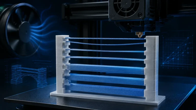
Proceed to ironing only when: the top stays closed without smoothing, has no obvious bulging and does not show broken paths. Persistent gaps despite adequate shell thickness call for another feeding/toolpath check. A visually closed surface does not verify strength. The bridging guide helps with poorly supported free spans; Prusa ironing documentation describes the additional smoothing process. Section checked October 13, 2026.
Ironing type: Top Surfaces or Topmost Surface?
| Mode | What gets ironed? | Best suited to |
|---|---|---|
| Top Surfaces | visible top regions at multiple Z heights | stepped housings, logos, multi-level parts |
| Topmost Surface | only the highest top surface | lids, plaques, simple boxes, saving time |
| All solid surfaces/layers | additional solid regions | special cases; potentially large time penalty |
For many everyday prints, Topmost Surface is the efficient first choice when only the final top plane matters. Use Top Surfaces when multiple visible levels need the treatment. Avoid enabling all solid layers by habit; it can multiply the extra toolpath area for very little visible benefit.
Ironing Flow: the most sensitive control
Ironing Flow is the small amount of additional extrusion delivered during the pass. It is expressed as a percentage relative to the normal extrusion reference and is surprisingly sensitive.
Too little effective flow often looks like:
- visible grooves between passes,
- matte or shiny bands following the original skin,
- shallow valleys remain unfilled,
- little improvement compared with ironing off.
Too much flow can cause:
- ridges or small waves,
- plastic being pushed toward the perimeter,
- smearing and torn-looking areas,
- material building up on the nozzle and dropping back onto the part.
Never interpret flow in isolation. If you reduce line spacing, the nozzle revisits the same area more often. A flow that worked at wider spacing can become effectively too aggressive.
Line spacing: smaller is not automatically better
Line spacing is the distance between adjacent ironing passes. OrcaSlicer recommends keeping it at or below nozzle diameter for useful coverage, while typical profile values are much tighter. The reason is overlap: the broad underside of the nozzle should sweep neighboring areas more than once.
Very tight spacing also increases:
- the number of passes,
- time spent by the hot nozzle over the surface,
- print time,
- the chance of pushing excess material when flow is too high.
Therefore, “0.05 mm must be better than 0.15 mm” is not a useful rule. The better target is as tight as needed for continuous coverage, but no tighter than necessary.
Ironing speed: why extremely slow can also hurt
Slower motion gives the nozzle more time to thermally and mechanically smooth the surface. Prusa therefore notes that slower ironing often works well. But “as slow as possible” is not universal.
At very low speeds the hot nozzle spends longer over each region. Depending on material, that can increase smearing, gloss variation or adhesion to the nozzle. At the same time, filament moves extremely slowly through the hotend. Both OrcaSlicer and Prusa warn about heat creep and possible clogging during long ironing passes, particularly with PLA and warm ambient/enclosure conditions.
Speed is therefore a fine-tuning control. If the surface is not fully covered, do not automatically cut speed in half. First inspect flow and spacing.
Inset: the overlooked perimeter control
Current OrcaSlicer provides an Ironing Inset that keeps the ironing toolpath away from outer contours. This can prevent material from being pushed directly over the edge.
A classic sign of too little inset combined with aggressive flow is a center that looks good while the perimeter becomes fuzzy, swollen or slightly overhanging. Increasing inset protects the edge but leaves a narrow non-ironed border, so it should be tuned together with flow rather than maximized blindly.
Angle Offset and Fixed Angle in modern OrcaSlicer
Modern OrcaSlicer goes beyond the old “iron at 45 degrees” approach. It exposes an Angle Offset and a Fixed Angle. A fixed angle uses an absolute ironing direction rather than only rotating relative to the top-surface direction.
This matters because reflected light can make alternating line directions appear as tiger-striping. Orca explicitly notes that a fixed direction can create a more uniform visual finish. With the common 45-degree solid-infill direction, 0° or 90° are suggested fixed-angle tests.
This is one reason older ironing tutorials are incomplete: current slicers can tune optical reflection and line-direction consistency, not just flow, spacing and speed.
Rectilinear or Concentric?
OrcaSlicer offers patterns including Rectilinear and Concentric. The choice affects both appearance and motion. Rectilinear is predictable and efficient on large rectangular surfaces. Concentric can visually suit round or organic top regions, but its path behaves differently near contours.
For calibration, start with a simple rectangular coupon using Rectilinear. Once flow, spacing and speed are stable, experiment with pattern and angle as deliberate visual design variables.
Materials: PLA, PETG, ASA, matte and silk do not react identically
Prusa explicitly notes that materials behave differently under ironing. PLA often irons very well but is more vulnerable to heat creep during long, slow passes. PETG can produce good surfaces but is more prone to sticking to the nozzle; accumulated polymer can overheat, darken and later deposit on the part. ASA can produce exceptionally smooth top surfaces.
For matte PLA and silk PLA, optical formulation matters as well:
- Matte filaments rely on diffuse light scattering, so ironing can create visible local gloss changes.
- Silk materials are highly sensitive to speed, temperature and flow state. A geometrically smooth surface is not automatically a uniformly glossy surface.
A material change is therefore a reason for a small re-test rather than blindly reusing the same process preset.
Layer height and nozzle size: why the same percentage may not transfer
OrcaSlicer notes that lower layer heights can require a different useful ironing flow because the percentage is not independent of the underlying extrusion geometry. The same applies to nozzle changes. A 0.6-mm nozzle is not simply a 0.4-mm profile enlarged; contact area, top-surface line width and sensible pass spacing all change.
Why large surfaces are harder than small coupons
A profile can look perfect on a 30×30-mm test tile and still fail on a large enclosure lid. Large ironed surfaces amplify:
- thermal drift over time,
- heat-creep risk,
- material accumulation on the nozzle,
- visible directional and reflection differences,
- the print-time penalty of very tight spacing.
The final validation should therefore use a surface that is at least reasonably representative of the real part.
A systematic ironing calibration workflow
- Make the top surface good without ironing. Flow Ratio, top-shell thickness, top speed and pattern must be correct first.
- Enable ironing with the existing profile values. Do not change three settings at once.
- Test flow. Move in small steps and watch for grooves versus pushed material.
- Optimize spacing. Reduce only until coverage becomes continuous.
- Fine-tune speed. Balance appearance with thermal behavior.
- Check inset. Pay special attention to swollen or fuzzy outer edges.
- Only then tune angle/fixed angle. At this stage the goal is mostly reflection and stripe direction.
- Validate at realistic part size.
Use a test matrix, not a “magic setting”
For a 0.4-mm nozzle, use the printer’s existing profile as the center of a small test matrix. If the preset is 10% flow, 0.15 mm spacing and 30 mm/s, do not jump straight to five unrelated recipes. First test flow slightly lower and higher. Keep the best flow and then vary spacing. Tune speed last.
| Symptom | Likely direction | Check first |
|---|---|---|
| Grooves remain visible | insufficient material / coverage | top skin, flow, spacing |
| Plastic is pushed ahead of the nozzle | too much material or thermal exposure | flow, speed, temperature |
| Perimeter becomes swollen | excess material at edge | inset, flow |
| Alternating matte/gloss stripes | direction or thermal variation | fixed angle, speed, material |
| Almost no improvement | ironing too weak or underlying skin is the problem | top skin, flow, spacing |
| Nozzle collects material | material sticks / flow too high / PETG behavior | nozzle, flow, temperature |
When ironing is the wrong solution
Ironing is strongest on flat horizontal top surfaces. It is not a universal surface-quality feature. It is less useful for:
- organic or steeply sloped surfaces,
- parts that can be oriented with the show face directly against a suitable build plate,
- very large surfaces where the time penalty is not worth the gain,
- functional contact surfaces where dimensional control matters more than appearance,
- materials that strongly stick to the nozzle or dislike prolonged heating.
Prusa makes a useful comparison: if orientation allows it, a bottom face produced directly against the build plate can be even smoother than an ironed top. Ironing is not automatically the best path to a smooth surface.
Ironing in multi-material prints
OrcaSlicer recommends Material Setting Overrides for multi-material prints because one ironing setup may not suit every material. This matters when different filaments appear on the same top region or when a toolchanger uses separate hotends.
A single global ironing preset for PLA, PETG and effect filaments conflicts with the material-specific nature of temperature, flow and cooling. Serious multi-material tuning should treat ironing the same way.
Heat creep: the unexpected ironing side effect
Ironing looks like a purely cosmetic feature, yet it can trigger a hotend problem. During long passes very little filament moves while the hotend remains fully heated. Residence time inside the thermal zone increases. OrcaSlicer and Prusa therefore explicitly warn about heat creep or clogging, especially on large surfaces and PLA.
If extrusion problems consistently begin during or immediately after a long ironing phase, do not investigate only retraction or nozzle blockage. Hotend cooling, ambient temperature and enclosure temperature belong in the diagnosis as well.
Our recommended OrcaSlicer workflow
- Calibrate Flow Ratio and the top surface first.
- Choose Top Surfaces or Topmost Surface intentionally.
- Start from the existing profile values, not an internet “best setting”.
- Calibrate flow in small steps.
- Reduce spacing only as far as necessary.
- Tune speed for both appearance and thermal behavior.
- Use inset to protect outer edges.
- Test Fixed Angle if changing reflection bands are visible.
- Re-validate after changing filament family or nozzle size.
Conclusion: ironing is a calibration, not a checkbox
A slicer’s default values are a sensible starting point, but they cannot know what your real top surface looks like. That is the core of the topic. Ironing becomes reliable when the underlying surface is already sound and flow, spacing, speed, edge behavior and direction are tuned systematically.
Current OrcaSlicer releases also expose more control than many older tutorials cover, including Inset, Angle Offset and Fixed Angle. Simply enabling ironing and copying somebody else’s flow setting leaves much of the feature’s potential unused.
FAQ: 3D printing ironing
What is the best ironing flow?
There is no universal value. Use the current printer profile as a baseline and move flow according to the visual symptom. Persistent grooves suggest insufficient effective coverage; pushed material suggests too much.
What line spacing should I use?
It should be tight enough for overlapping nozzle coverage. Tighter spacing also increases print time and thermal exposure, so reduce it only until the surface becomes continuous.
Is slower ironing always better?
No. Slower motion can improve smoothing but increases thermal residence time. On large PLA surfaces, extremely slow ironing can increase heat-creep risk.
Why can PETG look dirty after ironing?
PETG tends to stick to the nozzle more readily. Material can collect, overheat and later deposit onto the top surface. Keep the nozzle clean and avoid excessive ironing flow.
Should I use Top Surfaces or Topmost Surface?
Topmost saves time if only the highest face matters. Top Surfaces is useful when several visible plateaus at different heights need treatment.
Why do I see shiny bands?
Line direction can affect reflection in addition to flow and speed. Modern OrcaSlicer offers Angle Offset and Fixed Angle; a fixed direction can make some parts look more uniform.
Sources & current status
- OrcaSlicer Wiki: current Ironing quality settings
- Prusa Knowledge Base: Ironing
- Bambu Studio: current common process profile
- PrusaSlicer official open-source repository
Updated August 2026. Ironing options and bundled profile values can change with slicer releases and printer profiles. Values cited here are examples from current profiles, not universal material recommendations.