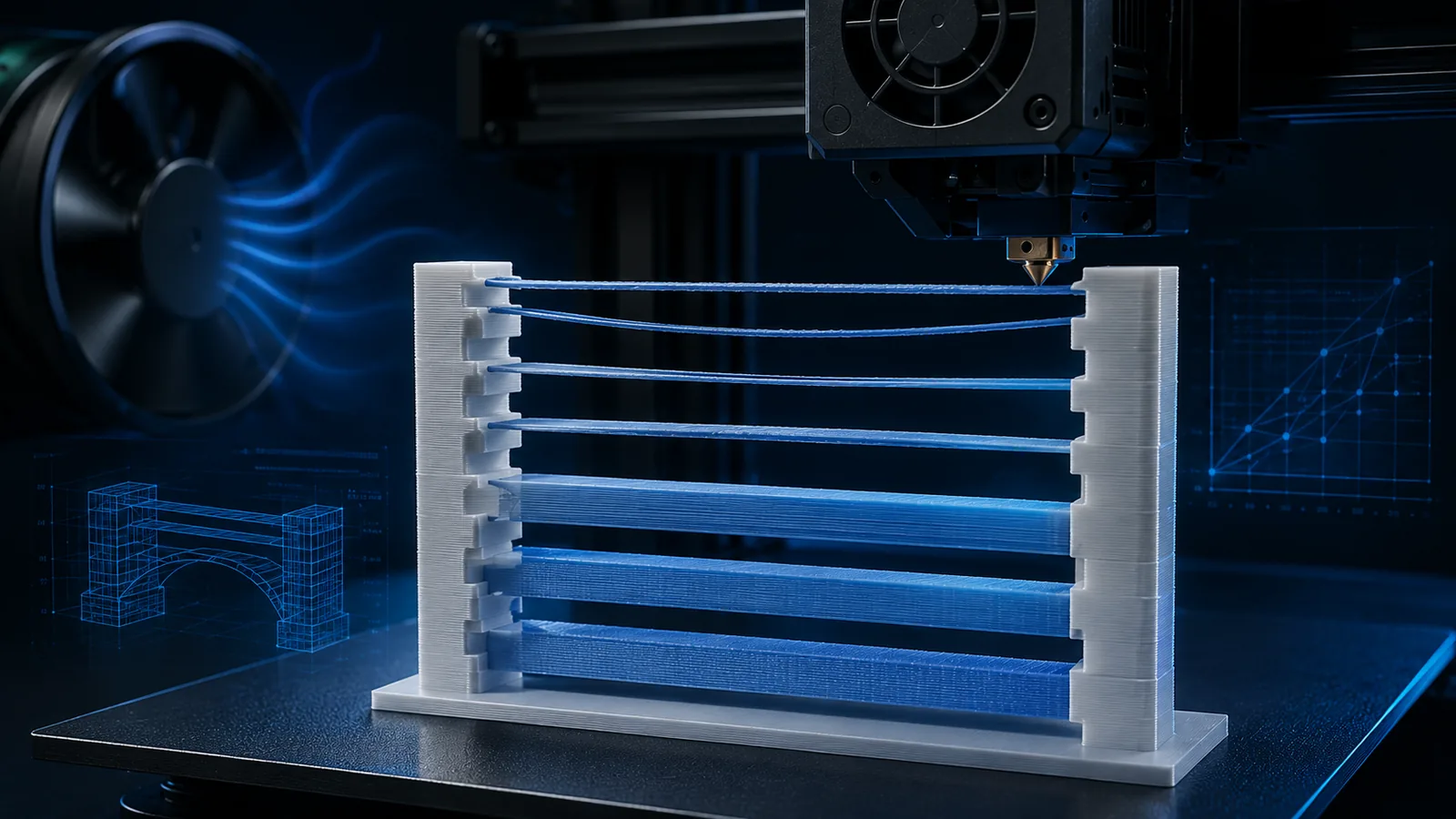
Bridges are one of the few places where an FDM printer truly prints across open air: an extrusion line is stretched between two supported areas with no previous layer directly underneath. Good bridges look effortless. Bad bridges sag, tear, become stringy, or leave the solid layers above them rough and uneven.
In current OrcaSlicer, bridging is no longer just one speed setting. Bridge Flow, Bridge Density, Thick Bridges, internal bridges, Extra Bridge Layers, Line Width, cooling and speed interact. This guide explains which control addresses which problem and why universal “magic settings” rarely work.
Bridge vs overhang: what is the difference?
With an overhang, at least part of the new extrusion line is still supported by the previous layer. A bridge spans a gap between supported regions. That distinction matters because OrcaSlicer can apply different speed and cooling rules.
- Overhang: partially supported; geometry, line width and cooling determine how far the line can extend.
- Bridge: unsupported over part of its path; the strand must behave like a tensioned fiber between two anchors.
- Internal bridge: the first solid layer over sparse infill or an internal void; reliability often matters more here than perfect underside appearance.
If you are unsure what OrcaSlicer actually classified as a bridge, inspect the sliced preview by feature/line type. A problem area is not automatically a bridge just because it appears to be “in mid-air.”
Overhangs and curling: cooling, layer time or missing support?
A bridge spans between supports; an overhang is only partly supported by the previous layer. Both can sag but do not necessarily need the same settings. Inspect detected path type, actual speed and cooling in preview. A nominal angle threshold is not a universal printing guarantee.
| Observation | Check | Compare separately |
|---|---|---|
| Only tiny tips or cross-sections soften | Layer time, achieved slowdown and fan behavior. | Material-appropriate layer time/cooling rather than only global speed. |
| Edges curl upward and the nozzle later touches them | Support beneath the path, local heat, overhang speed and cooling. | Stabilize the edge; stop contact before a shift occurs. |
| Underside sags while existing walls look sound | Orientation, layer height and support for the critical path. | Compare orientation or local supports. |
| One side is much worse | Airflow and orientation with the same profile. | Use an orientation change as a clue, not proof of a faulty fan. |
OrcaSlicer combines overhang speed with layer-time/cooling rules. Its overhang bands are expressed relative to line width. An overhang speed of 0 means no additional slowdown in that band, not a stopped move. Minimum print speed and outer-wall exclusions can limit how much small layers actually slow down. Inspect the sliced file.
Compare a section with the same critical geometry, orientation and material baseline. Change one relevant setting or the support first. More fan may improve a PLA overhang but is not universal advice for PETG, ABS/ASA or required layer bonding. If adhesion or layer connection deteriorates, a prettier underside alone does not make the change acceptable.
Change support or design when needed: cooling cannot rescue arbitrarily unsupported geometry. Make overhang printable changes geometry and needs deliberate assessment for dimension-critical areas. Accept a print only when collision-prone raised edges are resolved and underside quality and required function are suitable. Section checked October 13, 2026.
Start with the symptom: what does the bad bridge look like?
| Symptom | Likely direction | Check first |
|---|---|---|
| Strands sag softly downward | too hot, too much flow, too little cooling or too slow | temperature, Bridge Flow, fan, Bridge Speed |
| Strands snap or fail to reach the opposite side cleanly | too little material, too fast or poor anchoring | flow not too low, speed, geometry, start/end anchors |
| Visible gaps remain between bridge lines | Density/Line Width/Flow or preview interpretation | Bridge Density, Line Width, Thick Bridges |
| Bridge holds, but the surface above stays rough | first bridge layer does not support later solid layers well enough | Internal Bridge Density, Thick Bridges, Extra Bridge Layers |
| Only very long bridges fail | geometric limit has been reached | change orientation, add support or redesign |
Bridge Flow Ratio: separate external and internal goals
Orca documentation separates external and internal Bridge Flow. Lower flow can reduce external sag; higher internal flow can strengthen the foundation for later layers. It compounds filament flow.
This does not specify a universal target. If a strand is thin or loses its anchor, further reduction is the wrong direction. Inspect the internal bridge beneath rough upper surfaces first.
Bridge Density: inspect spacing and support in preview
Orca exposes separate external and internal density values. Density affects line spacing; higher and lower settings have different tradeoffs.
Lower density is not a general improvement. Check support for following layers, underside finish and actual paths. The official description explains separate behavior.
Thick Bridges: what “thick” actually means
With Thick Bridges enabled, OrcaSlicer uses a bridge extrusion height around the nozzle diameter. The freely suspended strand gets more cross-section and can span more reliably, especially over longer distances. The trade-off can be a rougher underside.
Current Orca documentation especially recommends Thick Bridges for internal bridges over sparse infill, where structural reliability is more important than a perfect visible underside.
- Thick Bridges ON: greater reliability and carrying capacity, especially internally or on longer spans.
- Thick Bridges OFF: may improve appearance on short, visible bridges.
This is therefore not a “newer is always better” switch. The correct choice depends on whether you are optimizing a visible underside or building a dependable base for later solid layers.
Extra Bridge Layers: choose by bridge type
The documentation lists disabled, external only, internal only and all bridges. Additional layers can support following layers.
Inspect whether another layer is actually generated and what supports it. This setting does not replace adequate anchors or a valid material profile.
Bridge Line Width: do not simply make it wider
Bridge extrusion behaves differently from a normal squished line. OrcaSlicer notes that Bridge Line Width should not exceed the nozzle diameter. Around 100% of nozzle diameter is a practical starting point in the current documentation.
If you deliberately use very wide inner walls elsewhere, that does not mean the same strategy is appropriate for freely suspended lines. For stronger bridge extrusion, Thick Bridges or Bridge Flow adjustment are the cleaner controls.
Bridge Speed: faster or slower?
There is no one-direction answer. Too fast can prevent the strand from anchoring well or cause it to break. Too slow keeps the hot nozzle over the unsupported strand longer and can give it more time to sag.
OrcaSlicer also separates external and internal bridges. Its current speed documentation generally suggests slower external bridges for quality, while internal bridges can run faster to reduce print time.
So do not cut bridge speed by 50% and assume quality must improve. Review together:
- Bridge Flow,
- material temperature,
- cooling,
- span length,
- start/end anchoring,
- and the actual speed in the slicer preview.
This connects to a broader principle we will cover separately: 3D printing can also become too slow.
Cooling: bridges often need more, internal bridges not always
With PLA and other materials that tolerate strong part cooling, higher airflow can stabilize the suspended strand faster. OrcaSlicer provides a dedicated Overhangs and external bridges fan speed setting.
Internal bridges are more nuanced. OrcaSlicer offers a separate Internal Bridges Fan Speed. Its current documentation notes that reducing internal bridge fan speed compared with normal cooling can help reduce warping when large internal areas would otherwise be cooled aggressively for a prolonged period.
Bridge direction: often more powerful than ten slicer values
The best bridge is often the shortest bridge. If rotating the model reduces a 40 mm span to 15 mm, that is usually more effective than extreme tuning.
A good bridge direction also needs reliable anchor areas at both ends. Short lines that start or end on a thin angled wall can be harder than a somewhat longer line stretched cleanly between two solid regions.
Before generating a forest of supports:
- Check model orientation.
- Inspect bridge direction in preview.
- Check the anchor areas.
- Only then fine-tune flow, speed and cooling.
Internal bridges and bad top surfaces
A common diagnostic mistake is to change Ironing or Top Surface Flow immediately when the top looks rough. If large sparse-infill areas sit below the visible top surface, the real problem may begin several layers deeper: the first internal bridge over the infill is not carrying well enough.
Then consider:
- Internal Bridge Density,
- Thick Internal Bridges,
- Extra Bridge Layers,
- infill geometry or infill density,
- and only after that top-surface settings.
This is also different from Ironing: Ironing works on an already existing visible top surface; it cannot repair an unstable foundation underneath.
Bridging and volumetric flow
Bridges do not usually run at the absolute throughput limit, but line width, layer height and speed are still physically linked. Use the Volumetric Flow Calculator to see what a combination requires. For general profile planning, the Nozzle, Layer & Speed Planner is useful as well.
If under-extrusion appears generally only at very high speeds, that points more toward MVS/hotend throughput than a bridging-specific problem.
Practical workflow: compare bridges under controlled conditions
First define the target: a visible underside or a reliable first layer supporting later solids. Appearance and load-bearing foundation are different goals. In preview, check external versus internal classification, actual direction, speed and anchor regions.
| Finding | Useful first comparison | Stop condition |
|---|---|---|
| Strands sag but remain connected | Compare a small Bridge Flow change or appropriate cooling | Do not keep reducing material once strands tear. |
| Strands fail to reach the other anchor | Check anchor areas, direction and speed | Do not hide a missing first anchor under more roof layers. |
| Bridge survives but upper surface remains rough | Inspect internal bridge and generated following layers | Do not change global top-surface settings without checking the foundation. |
| Only a long span fails | Compare orientation, anchors or support | A short coupon cannot approve every span. |
Start with reliable bed adhesion, a plausible filament profile and consistent feeding. General extrusion problems belong in the filament calibration workflow. Local bridge compensation should not hide an unstable overall profile.
A small comparison that supports a decision
Use a section matching the real span, anchor width, orientation, material and relevant following layers. Save the unchanged project. Change one setting and inspect preview again; nearby geometry can affect generated paths.
Illustrative example: A visible enclosure opening has a sagging underside. Compare its baseline against a small flow change first. If strands become too thin or lose their anchors, reject that change. Return to baseline and examine cooling or a shorter direction. For an internal bridge, also inspect the solid surface above it.
Record setting, actual span, direction, underside and following layers. Repeat an apparently better variant before saving it in the profile. If results vary, investigate conditions rather than changing several controls together. Section checked October 13, 2026.
When support is the better answer
Bridging has geometric limits. Very long spans, heavy cross-sections, unsuitable materials or a visible underside with a demanding finish may be better served by support.
The goal is not to force every design to print support-free. A good workflow decides whether orientation, bridge tuning, redesign or support is the most robust solution.
Conclusion
Good bridges come from the interaction of geometry, flow, speed and cooling. Thick Bridges are a tool for reliability, especially internally over sparse infill, but they are not a universal visual-quality mode for every exposed underside.
Once you distinguish between a bridge that truly fails and a bridge that merely provides a weak base for later layers, tuning becomes much more targeted. And often the most effective improvement is not an exotic slicer value at all, but a shorter span or better bridge direction.
Sources & current documentation
- OrcaSlicer Wiki – Bridging / Thick Bridges / Extra Bridge Layers
- OrcaSlicer Wiki – Line Width / Bridge Line Width
- OrcaSlicer Wiki – Cooling / External & Internal Bridge Fan
- OrcaSlicer Wiki – Overhang & Bridge Speed
Research checked: August 27, 2026. OrcaSlicer actively develops bridging features; names and behavior may change between releases.
Frequently asked questions
What are Thick Bridges in OrcaSlicer?
With Thick Bridges enabled, OrcaSlicer uses a larger bridge extrusion height around the nozzle diameter. This improves reliability and load-carrying ability but can make a visible underside rougher.
Should Bridge Flow always be set to 0.9?
No. OrcaSlicer gives a slight reduction such as 0.9 only as an example for sagging. The useful value depends on material, normal flow, nozzle, temperature and geometry.
Why can a bridge sag even when I slow it down?
Very slow bridging can also be unfavorable because the hot nozzle stays over the unsupported strand longer. Flow, temperature, cooling and anchoring should be checked together.
Why is my top surface rough even though the bridge below does not completely fail?
An internal bridge over sparse infill can be too weak to support later solid layers well. Internal Bridge Density, Thick Internal Bridges and Extra Bridge Layers may matter more than Ironing.
How wide should a bridge line be?
OrcaSlicer recommends around nozzle diameter as a starting point and notes that a freely suspended bridge line should not be set wider than the nozzle diameter.