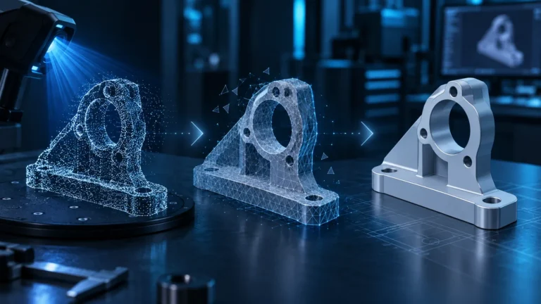
A point cloud contains measured points; a mesh describes surfaces between them. This guide takes an already registered point cloud to a checked working mesh. It cannot recover missing measurements or replace the subsequent CAD reconstruction in Fusion.
Preparation: inspect the input and define the purpose
Keep the scanner project and raw export. Check whether your file contains points or triangles: PLY can contain either. The extension alone is not enough. Unregistered captures must first be brought into a consistent coordinate system.
Identify the regions needed for shape, measurements or fits. Double edges and shifted views require fixing registration first. Meshing and smoothing cannot repair displaced coordinates. Missing capture of a functional surface calls for another scan.
1. Check units, scale and coverage
Open a working copy in the scanner application or CloudCompare. Compare several known dimensions in different directions and locations, using recognizable reference surfaces rather than noisy boundaries.
Review the front, back, underside, recesses and narrow edges. Color or texture does not establish complete geometry. Record missing areas before filtering so a later smooth reconstructed surface is not mistaken for actual measurements.
2. Remove surroundings and filter outliers conservatively
In CloudCompare, use Edit → Segment to select the relevant region. Inspect selections from additional directions before discarding points: a screen-space selection can also include hidden parts of the object.
For remaining isolated points, use Tools → Clean → SOR filter. It uses neighborhood distances statistically. Compare the output cloud with the original: thin ribs and poorly sampled edges can be removed along with unwanted points. A smaller standard-deviation multiplier is stricter; no setting suits every object.
Change one filter setting at a time. If real fine details disappear, keep a less aggressive version or remove identified bad points locally. Save this intermediate cloud separately from the eventual mesh.
3. Check normals and reconstruct the surface
CloudCompare’s documented Poisson workflow requires consistently oriented point normals. If missing, use Edit → Normals → Compute and check orientation afterward. Neighborhood selection must fit point spacing and shape; settings suitable for a broad smooth area can harm sharp features.
Select the cloud with normals and launch the installed Poisson Surface Reconstruction plugin. If unavailable, use a suitable installation or your scanner application’s mesh generation. More reconstruction detail does not automatically create more true measurements.
Poisson can extend into unmeasured areas. Compare the result with the input cloud. With density output enabled, inspect poorly supported boundaries and use Edit → Scalar Fields → Filter by Value to remove them. An open boundary is more truthful than an invented functional face.
4. Example: preparing a scanned enclosure
Illustrative example, not a scanner test: An enclosure has a mounting face and two fixing openings. Underside points are missing, and part of the turntable was captured beside it.
- Segment the turntable from multiple views without cutting away the enclosure base.
- After outlier removal, confirm that thin opening rims remain.
- Compute normals and a mesh. Compare any newly generated underside with the input points.
- A deliberately constructed closing surface may be acceptable for an unimportant display-model base. A missing mounting face needs another capture or independent dimensions.
- Do not automatically close fixing openings. For a functional model, verify their position and size and reconstruct them in CAD where appropriate.
The example ends with a documented distinction between measured and added surfaces, rather than simply “mesh closed.” A decorative print may tolerate an addition; a fitting replacement needs reliable functional dimensions.
5. Inspect the mesh before simplifying
Compare the mesh and cloud from several viewpoints. Look for bridges between separate surfaces, unexpected bulges, hidden foreign geometry and missing bores. Distinguish capture gaps from genuine openings; automatic hole filling must not erase an intended opening.
Direct printing also needs a slicer check for interpretable geometry and suitable wall thickness. A CAD reference instead prioritizes useful measured shape and need not be closed everywhere. See the scan-to-print guide for the printing branch.
Only then create a reduced working mesh. Compare critical edges, sections and dimensions before and after reduction, and preserve the dense archive. A universal triangle-count target cannot establish whether important geometry survived.
| Problem | Appropriate response |
|---|---|
| Double contours | Check registration instead of hiding them with smoothing. |
| Invented surfaces across gaps | Compare against input points; recapture functional areas. |
| Missing fine details | Filter or reduce less aggressively; compare raw data. |
| Closed bores | Correct locally and preserve intended openings. |
6. Archive output and decisions
Store the RAW project, cleaned cloud, dense mesh and reduced working mesh separately. Record units, reference measurements, processing settings and deliberately added surfaces. Export the variant required by the CAD or slicer task.
Preparation is complete when scale is checked, relevant surfaces remain intact, and missing or added regions are documented. If a check fails, return to the appropriate intermediate stage. Repeated smoothing of the final export cannot replace validation.
Sources and review date
- CloudCompare: Segment
- CloudCompare: SOR filter
- CloudCompare: Normals / Compute
- CloudCompare: Poisson reconstruction
- Open3D: Surface reconstruction
Documentation checked on October 13, 2026. Menu labels and available tools depend on language, version and installation. The example is not a documented product test.
Frequently asked questions
Is the example a hands-on test?
No. It is an illustrative workflow example without measured test results.
When is another scan needed?
When relevant functional surfaces are missing or registration cannot be reliably corrected. Smoothing does not replace measurements.
Must a CAD reference mesh be closed?
Not everywhere. Relevant measured surfaces matter; direct printing needs additional checks.