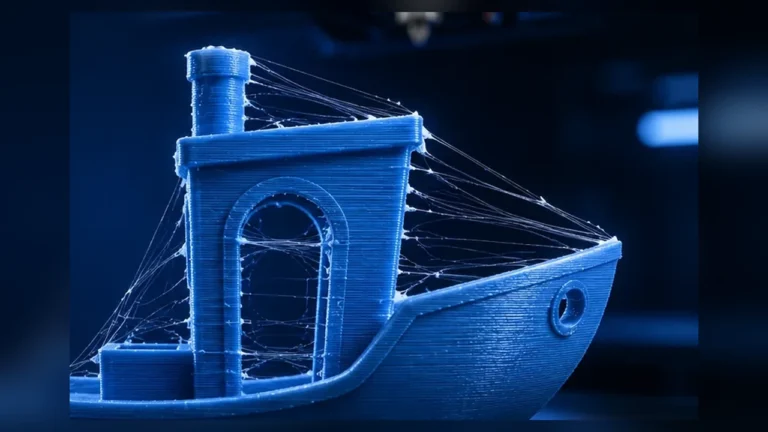
A single horizontal bulge at one specific height is not automatically Z wobble, over-extrusion or a loose belt. If the line appears exactly where geometry, wall thickness, infill, top layers or layer time changes sharply, you may be looking at a Hull Line – commonly called the Benchy Hull Line or, on boxes and containers, a Box Bulge Line.
What is a Hull Line in 3D printing?
A Hull Line is a visible horizontal line, step or slight bulge on an outer wall caused by an abrupt change in printing conditions. The classic example is the 3DBenchy around deck height: below and above that zone, geometry, material per layer, print time and cooling behavior change significantly.
The effect is not limited to Benchy. It also appears on boxes, containers, housings and functional parts – for example where a thick solid floor transitions into thin side walls, where a large top surface ends or where the amount of solid infill changes suddenly.
Why does the bulge appear?
FDM plastics shrink as they cool. When consecutive layers experience similar thermal conditions, that shrinkage stays relatively consistent and is difficult to see as one isolated line. But if layer time or thermal mass changes abruptly, one layer can cool and contract differently from the layers around it. Already solidified geometry constrains that movement, creating local stress and a visible contour change.
This is why current slicer discussions and issue reports repeatedly connect Hull Lines with shrinkage, internal stress, layer-time spikes and transitions between sparse infill, solid infill and top layers.
1. Sudden layer-time changes
A large solid area or top surface can take much longer to print than the layers immediately before or after it. During that extra time, previously deposited plastic continues to cool and contract. The following layer then starts on geometry with a different thermal state.
2. Unequal thermal mass
A thick floor contains far more material per millimeter of height than a thin wall. More hot plastic stores more heat and later has more shrinkage potential. An abrupt thick-to-thin transition can therefore affect the outer wall even though the CAD contour itself is perfectly straight.
3. Internal stress reaches the outer wall
The visible line does not necessarily mean the outer wall was simply “extruded wrong”. Internal solid layers, top surfaces and geometry transitions can pull on an already printed shell as they cool, locally changing the outside contour.
4. Flow dynamics can amplify the defect
If toolpaths and speeds change heavily at the same height, extrusion dynamics change too. Poorly tuned flow or Pressure Advance may make an existing Hull Line more visible, but Pressure Advance is not the root cause of every Hull Line.
How to identify a real Hull Line
| Clue | Hull Line | More likely another problem |
|---|---|---|
| Position | one or a few fixed heights | regular repetition over Z → Z-banding |
| Geometry link | often matches floor, deck, opening, infill/solid transition | no geometry link → inspect mechanics/extrusion |
| Shape | continuous line or shallow bulge | whole contour jumps sideways → Layer Shift |
| Pattern | single thermal transition | waves after corners → Ringing/Ghosting |
| Wall thickness | local change | everything too thick → Flow/over-extrusion |
The most useful test: inspect the slicer preview at that exact height
Before disassembling hardware, open the preview in OrcaSlicer, Bambu Studio, PrusaSlicer or your preferred slicer. Compare the layers directly below, at and above the visible line:
- Layer Time: is there a sharp spike or drop?
- Speed: do outer wall, solid infill or top-surface speeds change heavily?
- Fan Speed: does cooling change at the same height?
- Flow / Volumetric Flow: does material throughput change substantially?
- Feature Type: does a top surface, bridge, internal solid infill or thick region start or stop here?
If the physical defect lines up exactly with one of these transitions, that is a much stronger Hull-Line clue than a generic suspicion of the Z axis.
Hull Line vs. Z-wobble / Z-banding
Mechanical Z-banding usually repeats. A bent lead screw, cyclic bearing problem or repeating drive error tends to create a pattern across multiple heights. A Hull Line is much more likely to stay attached to a model or slicer transition.
A simple tower or box with a constant cross-section is therefore a useful control print. If it is clean while the complex model develops the same line at the same geometry height, classic periodic Z error becomes less likely.
Hull Line vs. Layer Shift
With a Layer Shift, the contour from one layer onward is laterally displaced. A Hull Line mainly changes local wall shape or thickness while the print above continues at the correct XY position. A nozzle collision can of course cause a real shift as a separate problem, so inspect the geometry of the defect carefully.
Hull Line vs. Ringing / Ghosting
Ringing appears as repeated waves after corners, holes or abrupt direction changes. It is not simply one horizontal line wrapping around the model. If the same wave pattern follows many sharp features, inspect mechanics, acceleration and input shaping instead.
Hull Line vs. over-extrusion
Global over-extrusion makes walls, top surfaces and corners generally too material-rich. A Hull Line is height-specific. Flow calibration is still useful, but do not reduce extrusion factor simply because one isolated height has a bulge.
What actually helps?
There is no universal “Hull Line setting” because geometry, material, temperature, layer time and cooling interact. Use a controlled test sequence instead.
1. Reduce abrupt layer-time changes
Check whether one feature is printed dramatically slower than its neighbors. Large differences between outer walls, solid infill and top surfaces can change the thermal rhythm of the part. The goal is not to force every feature to the same speed, but to avoid extreme jumps where practical.
2. Keep cooling consistent
Large fan-speed changes can amplify the effect, especially when a feature is suddenly treated as a bridge or overhang. Inspect the fan preview at the Hull-Line height. With PLA, controlled cooling may help equalize thermal conditions; with ABS/ASA, a warm stable chamber is often more important than aggressive part cooling.
3. Avoid unnecessarily high nozzle temperature
Excess temperature increases the amount of heat introduced into the part and can exaggerate thermal differences. If flow and layer adhesion allow it, test a slightly lower temperature. Do not go so low that volumetric flow or bonding becomes unreliable.
4. Test wall order
On some geometries, changing wall order can stabilize the outer surface. Outer-first or Inner/Outer/Inner approaches are often discussed as possible reduction methods. They can also affect overhangs and seams, so test them on the actual model instead of applying them globally.
5. Use enough walls without making the part unnecessarily massive
A very thin shell is more easily influenced by stress from the interior. Additional perimeters can stiffen the wall and reduce visible deformation. But simply making everything solid can increase thermal mass and create a different version of the same problem.
6. Design infill and solid regions deliberately
A high-density region directly below a thin wall can create a hard thermal transition. Lower infill, a different pattern or more gradual material distribution may help – provided the functional strength of the part is still adequate.
CAD changes can be more effective than slicer tuning
For your own designs, the strongest fix may be to soften the geometry transition. A 6 mm solid floor that instantly becomes a 1.2 mm wall creates very different thermal conditions from a more gradual design.
- avoid unnecessarily massive floors
- change wall thickness progressively where possible
- use internal radii or chamfers at abrupt transitions
- avoid rigidly tying large internal solids directly to cosmetic outer walls when unnecessary
- use localized reinforcement instead of large solid blocks
On housings and boxes, a small structural separation between the visible shell and a massive internal feature can reduce how much shrink stress transfers to the outside. Whether that is mechanically acceptable depends on the part.
Material matters
Materials with stronger thermal shrinkage can show Hull Lines more clearly. ABS/ASA and some engineering polymers are more sensitive to uneven cooling than well-cooled PLA. Silk and glossy filaments can also make small contour or gloss changes far more visible.
For meaningful A/B tests, keep the same spool, orientation and environment. A different material may hide the line without proving that the original profile was fundamentally wrong.
A reproducible diagnostic workflow
- Measure the height: record where the line appears in millimeters.
- Open the slicer preview: inspect Layer Time, Speed, Fan, Flow and Feature Type.
- Check geometry: does a floor, deck, opening, top surface or solid infill start/stop there?
- Print a simple control object: use constant geometry with the same profile.
- Change one variable: layer-time/speed behavior, cooling or temperature.
- Modify CAD only after that: if the artifact remains tied to the same design transition.
What not to do first
- disassemble or lubricate the Z axis on suspicion alone
- drop flow heavily when only one height is affected
- recalibrate Pressure Advance before checking layer-time changes
- change cooling, speed and temperature all at once
- accept the defect as “normal” without checking the slicer preview
Can a Hull Line be eliminated completely?
Sometimes, but often the realistic goal is to reduce it substantially. Complex parts can never be perfectly free of thermal stress. The practical target is a controlled transition where the effect is visually and functionally insignificant.
If repeated tests keep producing the line at exactly the same CAD transition, redesigning that transition is often more efficient than endlessly tuning unrelated slicer settings.
Conclusion
A Hull Line is a geometry-and-thermal print artifact, not one magical slicer setting. The fastest route to a correct diagnosis is the defect height itself: inspect Layer Time, Speed, Fan and Feature Type, then distinguish Hull Line from Z-banding, Layer Shift, Ringing and global over-extrusion.
Sources & further reading
- Factorian Designs – The Most Misdiagnosed Print Error: Hull / Shrink / Wall Lines
- PrusaSlicer Issue #9272 – Hull Line, Layer Time and Shrinkage
- Bambu Studio Issue #9027 – Hull line artifacts from infill-to-solid transitions
- Bambu Lab Community – Benchy Hull Line, cooling and layer-time discussion
Updated August 2026. Community and issue sources document reproducible observations and troubleshooting approaches; they are not universal printer profiles.
Frequently asked questions
Is a Hull Line the same as Z-wobble?
No. A Hull Line is usually tied to a specific geometry or layer-time height. Mechanical Z-banding more often repeats periodically over multiple heights.
Why is the Hull Line so visible on 3DBenchy?
Around deck height, Benchy changes toolpath and thermal conditions significantly. Layer time, solid/top regions and cooling behavior can change enough to make shrinkage differences visible.
Can more cooling remove a Hull Line?
More consistent cooling can help on some materials, but more fan is not universal. ABS/ASA often benefit more from a stable warm chamber than aggressive part cooling.
Does Outer Wall First fix Hull Lines?
Different wall order can reduce the artifact on some models, but it also changes overhang and seam behavior. Treat it as a controlled A/B test, not a universal setting.
Should I service the Z axis when I see a Hull Line?
Not automatically. If the line matches a geometry/layer-time transition and a simple control print is clean, investigate thermal and slicer transitions first.