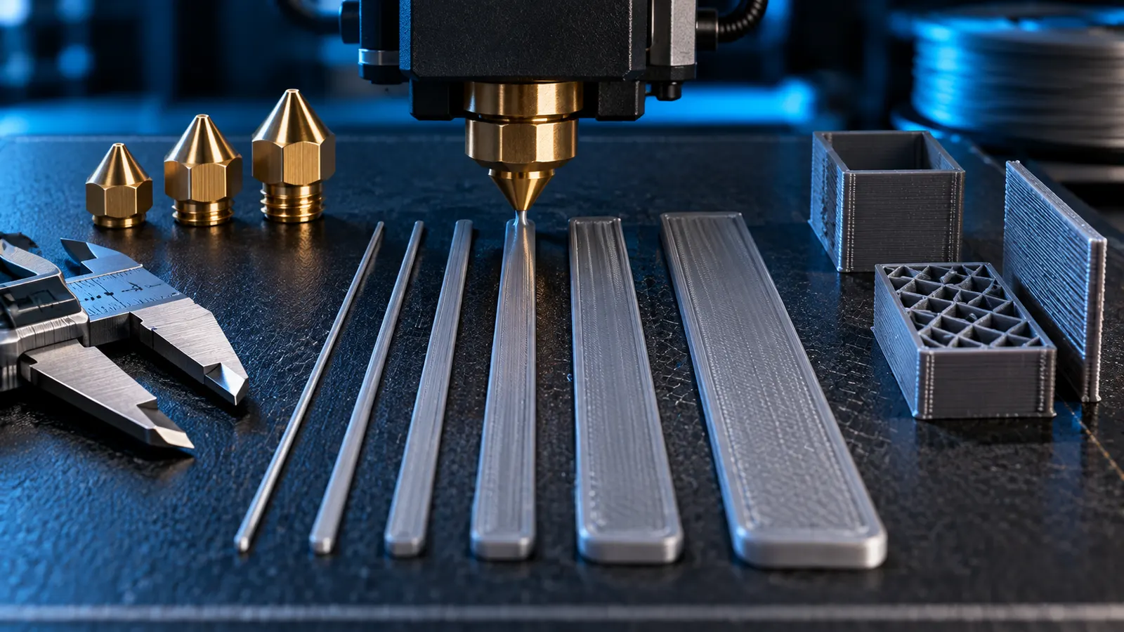
A 0.4 mm nozzle does not have to print only 0.40 mm wide lines. In the slicer, line width / extrusion width can be set narrower or wider for different print features, and modern wall generators such as Arachne can vary it dynamically to fit the model geometry.
This flexibility is useful because wider extrusion can strengthen inner walls or infill, while visible outer walls and top surfaces often benefit from more conservative values. At the same time, wider lines increase required volumetric flow. So “wider = stronger and faster” is only true within the limits of the hotend and geometry.
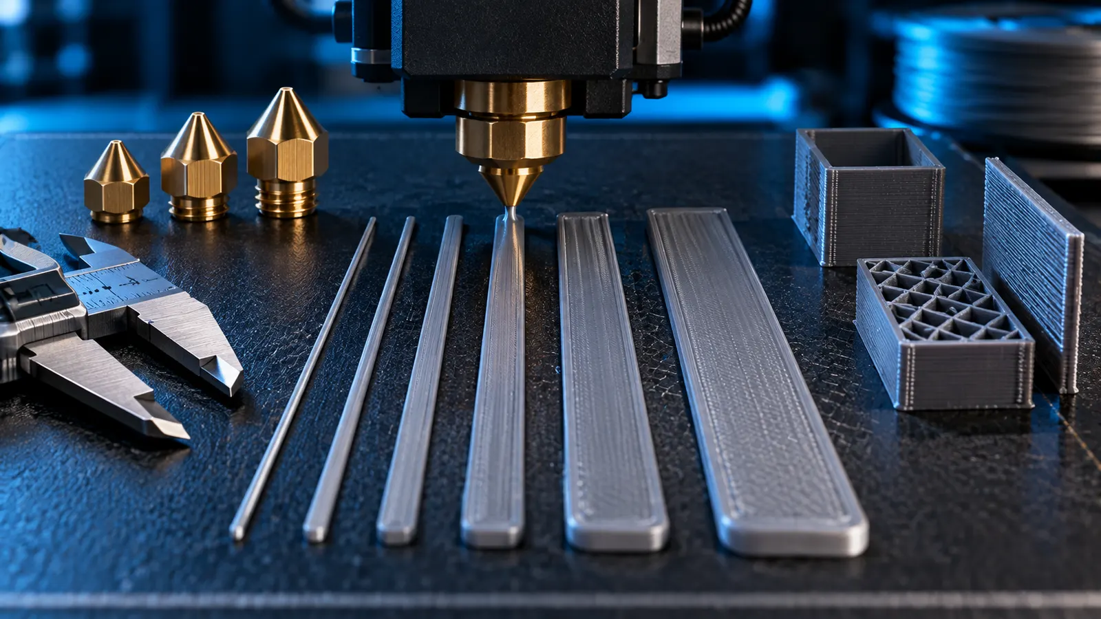
Nozzle diameter and line width are not the same thing
Nozzle diameter is the physical opening in the nozzle. Line width is the target width of the extruded road after it is deposited onto the previous layer.
Molten filament leaves the nozzle with a rounded cross-section and is then flattened as it is laid down. That is why an extrusion can be wider than the nozzle opening, and why many profiles use extrusion widths around the nozzle diameter or slightly above it.
| Term | Meaning | Example |
|---|---|---|
| Nozzle Diameter | physical diameter of the nozzle opening | 0.4 mm |
| Line Width / Extrusion Width | target width of the deposited road | for example 0.42–0.48 mm |
| Layer Height | vertical height of one layer | for example 0.20 mm |
How wide can a 0.4 mm nozzle really print?
There is no single magic maximum for every nozzle and material. Current OrcaSlicer documentation provides a useful practical frame: 100% of nozzle diameter is a good starting point; going significantly below 100% can hurt adhesion between roads, while values above roughly 150% can produce over-extrusion, blobs or poor surface quality.
For a 0.4 mm nozzle, that gives a rough practical range like this:
| Line width | Relative to 0.4 mm nozzle | Practical interpretation |
|---|---|---|
| 0.36 mm | 90% | narrow; special case, verify bonding and consistency |
| 0.40 mm | 100% | solid reference value |
| 0.42–0.48 mm | 105–120% | useful range for many features |
| 0.50–0.56 mm | 125–140% | wide; more suited to inner walls/infill with flow reserve |
| 0.60 mm | 150% | upper-end special case, not ideal for every feature |
This is not a universal approval table. Hotend capability, material, layer height, speed and geometry all determine whether a wide road prints cleanly.
Outer wall, inner wall and top surface should not all use the same width
OrcaSlicer allows feature-specific line widths because a visible outer wall has different goals from an inner wall or sparse infill.
| Feature | OrcaSlicer guidance | With a 0.4 mm nozzle | Main goal |
|---|---|---|---|
| Outer Wall | 105–120% | 0.42–0.48 mm | surface quality, dimensions, overhangs |
| Inner Wall | typically ≥120% | about 0.48 mm and up | more material per wall, strength |
| Top Surface | 100–105% | 0.40–0.42 mm | smooth visible top layers |
| Sparse Infill | about 115% | about 0.46 mm | good bonding without excessive flow demand |
| Support | about 100% | about 0.40 mm | balance of strength and removability |
| Bridge | about 100%, not wider than nozzle | about 0.40 mm | stable free-spanning strand |
These are current OrcaSlicer starting recommendations, not mandatory values for every profile.
Why wider lines can improve strength
A wider extrusion can create more contact area with the neighboring road and the layer underneath. For inner walls and infill, this can improve bonding and fill a given wall thickness with fewer individual passes.
That can also reduce toolpath count. A 1.2 mm wall may sometimes be filled more efficiently with two wider roads instead of three 0.4 mm roads. Whether that actually saves time still depends on the available volumetric flow.
Wider line width increases volumetric flow
The most important side effect is easy to miss: a wider road needs more plastic per second at the same layer height and speed. As a useful approximation, required flow scales with:
Line Width × Layer Height × Print Speed
The real extrusion cross-section is not a perfect rectangle, but the approximation makes the trend clear. Moving from 0.40 to 0.56 mm substantially increases material demand per distance travelled.
That is why wide extrusion should always be considered together with Max Volumetric Speed (MVS) and real feature speed. Our Nozzle / Layer / Speed Planner helps sanity-check the combination.
When does a narrower line make sense?
A narrower line can help when geometry cannot be represented cleanly by a wider road, such as small gaps, narrow ribs or fine outer contours.
But a 0.4 mm nozzle should not simply be treated as a reliable 0.25 mm nozzle in software. The further the target width moves away from the physical nozzle, the more sensitive extrusion becomes to flow, pressure control and geometry.
If fine XY detail is regularly important, a real 0.2 or 0.25 mm nozzle is usually the more robust solution. That is why our FDM miniatures guide treats small nozzles separately.
Arachne changes the rules
With the Classic wall generator, a configured line width is comparatively direct. Arachne treats it more as a reference and dynamically varies extrusion width to fit local geometry.
This is especially useful for thin walls and changing wall thickness. A single nominal line width therefore describes the real toolpaths less precisely in Arachne than in Classic.
For a deeper explanation, see our Arachne guide.
PrusaSlicer: similar idea, different details
PrusaSlicer also separates nozzle diameter from extrusion width. Its current documentation suggests roughly 110% of nozzle diameter as a general orientation. If Default Extrusion Width is set to 0, PrusaSlicer derives it automatically and documents a value of 1.125 × nozzle diameter.
For the first layer, Prusa also describes wider extrusion around 120–140% as a way to improve bed adhesion, with the explicit trade-off of lower XY resolution.
First layer: wider can help, but it cannot fix everything
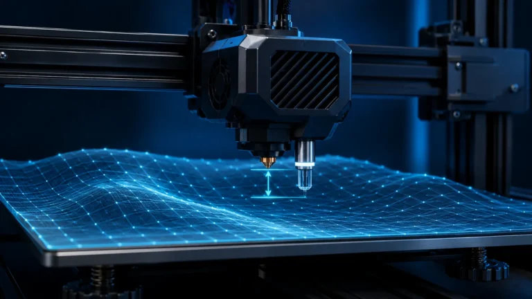
A slightly wider first layer can improve bed adhesion and tolerance to small surface variation. It does not replace a correct Z Offset, Bed Mesh or first-layer setup.
If the nozzle is too low, more width can worsen elephant foot. If it is too high, a wider road does not reliably solve the underlying reference error either.
Bridges are a special case
Bridge extrusion hangs in free air and is not squashed onto the previous layer like a normal road. OrcaSlicer therefore recommends a bridge line width around the nozzle diameter and notes that it should not exceed the nozzle diameter.
If bridges are weak or sagging, bridge flow, speed, cooling and Thick Bridges are usually better controls. See our Bridging guide for the full workflow.
0.4 mm nozzle with 0.6 mm line width: sensible or not?
Yes, it can work in selected situations. A 0.60 mm road equals 150% of a 0.4 mm nozzle, which is right at the upper boundary where OrcaSlicer warns about increasing risk of over-extrusion, blobs and poor surface quality.
I would therefore not use 0.60 mm as a universal default for a 0.4 mm nozzle. It is more suitable for robust internal structures when:
- the hotend has enough volumetric-flow headroom,
- flow ratio and pressure advance are calibrated,
- speed matches the flow demand,
- the geometry supports wide roads,
- visible surface quality is not the primary goal.
When is a larger nozzle the better choice?
If you routinely want very wide extrusion, a larger nozzle is often better than running a small nozzle at the top end of its line-width range.
A 0.6 mm nozzle is not only a larger opening; it is also intended for larger material throughput and higher useful layer heights. It is attractive for large functional parts, thick walls and faster printing, with the trade-off of less XY detail on small features.
Nozzle diameter therefore still defines the physical process class. Line width is flexible within that class, not a full replacement for changing the nozzle.
Infill-to-wall contact: gap, low flow or too much overlap?
A wider infill line does not automatically improve wall bonding. The generated path must reach the wall and then extrude reliably. Inspect a representative section in preview and on a cooled comparison part before increasing flow or overlap.
| Observation | Check | Appropriate next change |
|---|---|---|
| Paths already missing in preview | Geometry, wall generator, local width and generated contact. | Fix path generation; more global flow cannot create a missing path. |
| Paths planned but printed thin or broken | Infill speed, MVS, filament path and feeding. | Reduce throughput demand before increasing contact settings. |
| Clean sparse infill but gaps at the wall | Actual Infill Wall Overlap and generated contact. | Change overlap modestly and compare again. |
| Gap only between the top skin and wall | Top/bottom infill-wall overlap. | Use the shell contact setting rather than the wrong infill field. |
| Raised material or infill marks on visible walls | Excess overlap, wall structure and flow separately. | Reduce contact material or review the wall structure. |
OrcaSlicer distinguishes Infill Wall Overlap from Top/Bottom Infill/Wall Overlap for shell regions. Similarly named fields are not interchangeable. Check the percentage definition and re-slice after width changes: the same percentage does not imply the same nominal overlap distance at every line width.
Controlled comparison: keep geometry, material baseline, orientation and wall count constant. Establish plausible feeding, then change only width or overlap. Accept the change when paths no longer visibly break at the junction and no new ridges, scraping or show-through appear. Visible contact does not verify bond strength or part performance.
Raised infill crossings are different from missing wall contact; inspect the pattern and actual toolpath for that problem. More infill density or global flow can introduce new faults. For throughput issues, use the MVS guide. Section checked October 13, 2026.
Common line-width mistakes
| Mistake | Why it causes trouble | Better approach |
|---|---|---|
| setting every feature to 150% | visible surfaces, bridges and small details suffer | use feature-specific widths |
| going wider without checking MVS | hotend reaches its flow limit | check flow and speed together |
| using narrow width instead of a small nozzle | process becomes sensitive, detail gain is limited | use a smaller nozzle for consistently fine detail |
| copying Prusa/Orca percentages 1:1 | percentage reference can differ | check the field definition |
| treating Arachne like Classic | actual toolpath width can vary dynamically | inspect Preview |
| fixing first layer only with width | Z reference problem remains | set Z Offset and first layer correctly first |
Practical workflow: change one feature width deliberately
Start from a working profile and a representative part section. Change only inner walls or infill first when targeting internal efficiency. Outer walls, top surfaces and bridges need separate acceptance criteria.
Orca documentation distinguishes feature widths and dynamic Arachne adjustment. The entered width is then a reference, not a guarantee for every path. Inspect generated wall count, local widths, closed thin regions and effective volumetric flow in preview.
| Goal | Inspect in preview | Inspect on the part |
|---|---|---|
| Reduce travel paths | Is the wall filled appropriately and does path count actually fall? | Contours, transitions and fits. |
| Print wider internal structures | Does MVS reduce speed after the change? | Extrusion, road bonding and intended function. |
| Preserve fine geometry | Which details does the wall generator actually produce? | Presence and robustness of small features. |
| Improve finish | Was only the relevant feature changed? | Better finish without new local buildup. |
Calculation example: wider does not automatically mean faster
Illustrative approximation: At 0.20 mm layer height and 150 mm/s, 0.45 mm width gives 13.5 mm³/s. At 0.60 mm it gives 18.0 mm³/s. For an assumed MVS limit of 15 mm³/s, about 125 mm/s is the wider road’s limit in this simple rectangular calculation.
This is neither measured printer performance nor complete slicer extrusion geometry. Real cross-sections, Arachne, acceleration and feature rules affect the result. Fewer roads printed more slowly may save less time than expected or none. The sliced file is what matters.
Compare baseline and changed projects with the same orientation and material basis. Keep the change only after checking finish, fit and function; a visually closed wall does not prove strength. The flow calculator provides the approximation, and the high-speed guide explains constraint decisions. Section checked October 13, 2026.
Conclusion
Line width and nozzle diameter are related, but they are not the same setting. A 0.4 mm nozzle can sensibly print roads wider than 0.40 mm. For many features, moderate values around 105–120% are useful, while very wide extrusion should remain a targeted special case.
The key is the combination: line width affects detail, strength, surface quality, print time and especially required volumetric flow. It should never be tuned in isolation.
To plan a nozzle, layer-height and speed combination, use our Nozzle / Layer / Speed Planner and check Max Volumetric Speed for high-throughput profiles.
Sources & current status
- OrcaSlicer Wiki – Line Width
- OrcaSlicer Wiki – Mixed Nozzle Sizes
- Prusa Knowledge Base – Creating profiles for different nozzles
- Prusa Knowledge Base – Experimental printing with different nozzle diameters
Research status: September 18, 2026. Useful line widths depend on material, hotend, wall generator, layer height, speed and model geometry.
Frequently asked questions
Can a 0.4 mm nozzle print a 0.6 mm line width?
Yes, in selected situations. 0.6 mm is 150 percent of the nozzle diameter, so it is better treated as an upper-end special case than a universal default.
What line width should I use with a 0.4 mm nozzle?
100 percent of nozzle diameter is a good starting point. Many features work well around 105 to 120 percent, while top surfaces and bridges are usually more conservative.
Does a wider line make a print stronger?
It can improve contact area and bonding, especially for inner walls, but it also increases material throughput and volumetric-flow demand.
Can I use a very narrow line with a 0.4 mm nozzle for more detail?
Only to a point. As width moves well below nozzle diameter, extrusion becomes more sensitive. A smaller nozzle is usually more reliable for consistently fine XY detail.
Why does Arachne change my line width?
Arachne dynamically varies extrusion width to fit model geometry. The configured line width acts more like a reference than with the Classic wall generator.