A helmet, armor piece, large figure or enclosure can look perfect and still be larger than the build plate. At that point, simply cutting the STL somewhere is not enough. Scale, cut position, connectors, clearance and print orientation all determine whether the sections will align cleanly after printing.
The most important rule is: set the final size first, then split the model. If already-separated parts are scaled independently later, dimensional errors are built directly into the mating surfaces.

1. Scale first, cut second
For large models, the order of operations matters:
- inspect the model at its original size,
- define the target dimensions,
- scale uniformly while proportions should stay unchanged,
- only then create the final cuts,
- add connectors and clearances to the final scaled geometry.
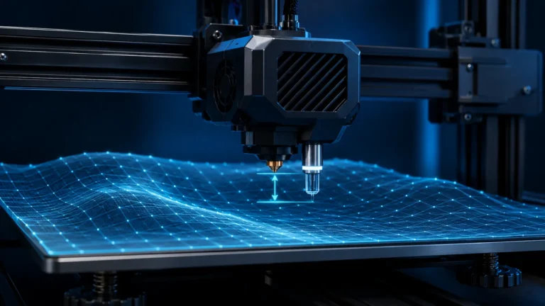
Our 3D Scale & Fit Calculator can calculate a consistent scale factor from original and target dimensions and also check the printer build volume.
Helmets and armor: use target dimensions, not guesswork
For wearable parts, “110% looks about right” is rarely enough. A helmet has several important internal dimensions, including usable width, depth and height. You may also need room for padding, hair, glasses or the way the helmet passes over the head.
A single head measurement is therefore only a starting point. Check the tightest relevant internal contour, not just the external bounding box.
| Use case | Better approach |
|---|---|
| display model | uniform scale to the desired overall size |
| wearable helmet | check internal width, depth and opening against real measurements |
| armor piece | include movement and padding clearance |
| functional enclosure | use installed components and mounting points as references |
Uniform scale or separate X/Y/Z scaling?
Uniform scaling is the safe default because all proportions stay intact. Separate X/Y/Z scaling can be useful for wearables when a model is tall enough but too narrow, for example. However, it changes angles, radii, wall thicknesses and any designed fits.
Use non-uniform scaling deliberately and re-check critical geometry afterwards. Never scale only one half of a mating assembly.
2. Cut placement matters more than the number of pieces
Large models can often be printed as a few big sections or many smaller ones. Fewer parts mean fewer seams, but larger print failures are more expensive. More sections are easier to orient and cheaper to reprint individually.
A good cut location should satisfy several goals at once:
- each section fits comfortably on the bed,
- the new face may provide a useful print surface,
- major visible surfaces are not cut unnecessarily,
- the seam follows a natural edge or an area that is easy to finish,
- there is enough material around the connectors,
- the cut does not leave extremely thin walls.
PrusaSlicer supports planar cuts, dovetail cuts and generated connector/dowel geometry in its Cut tool. Bambu Studio also provides a Cut tool with connectors; exact connector types and interface details can change with slicer versions.
Hide seams deliberately
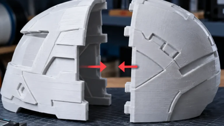
For helmets and large figures, existing design lines are useful: panel gaps, armor transitions, belts, bases and hard surface boundaries hide a joint much better than a seam through a smooth visible panel.
But the best-looking seam is not automatically the best print seam. If that choice forces huge supports or a fragile orientation, a slightly more visible but printable split can produce a cleaner finished part.
3. Connectors: dowels, plugs, dovetails or simple pins?
Connectors have two jobs: align the sections and optionally support the bonded joint mechanically. They should not replace a sufficiently large, clean mating surface.
| Connector | Strength | Typical use |
|---|---|---|
| round dowels / alignment pins | simple, robust, easy to test | helmets, figures, enclosures |
| polygonal plugs | adds rotational indexing | larger sections with a fixed orientation |
| dovetail | guides along the cut surface | long, accessible seams |
| magnets / screws / inserts | can remain removable | service access, detachable panels |
Connector clearance: do not copy a universal number
A common mistake is treating an online clearance value as universal. Real fit depends on printer, material, flow, XY compensation, part orientation and cooling.
A better method is a small fit coupon using the same connector geometry and orientation with several stepped clearances. In a short test you can identify press fit, sliding fit and glue fit for your own setup.
The same logic helps when already-split parts do not line up after printing. Our guide “Split 3D Printed Parts Don’t Fit” separates Flow Ratio, Elephant Foot, shrinkage, warping and clearance problems.
4. Re-evaluate orientation for every section
After splitting, each section is its own print. Do not automatically keep the original orientation. For every part, check:
- which surface can provide a stable base,
- where supports would damage the visible surface,
- how layer direction relates to mechanical load,
- whether long narrow areas are prone to warping,
- whether the mating face is likely to remain flat.
On helmets, a new cut face can become an excellent print surface. Conversely, a thin shell printed vertically may need little support but can be more sensitive to warping or vibration.
5. Scaling also changes wall thickness and details
Scaling an STL changes more than its outside dimensions. A 2 mm wall becomes 1 mm at 50% scale; a designed 0.3 mm gap becomes 0.15 mm. Printer error and material shrinkage do not automatically shrink by the same factor.
This matters especially for:
- plug connections,
- screw holes and threads,
- snap fits,
- thin edges,
- magnet pockets,
- pre-designed alignment pins.
Large scale changes can therefore alter the function of geometry even when the model still looks correct in the slicer.
6. Why perfect digital cuts can still misalign after printing
Perfect mating geometry in the STL does not guarantee an invisible physical seam. Large FDM parts can deform slightly as they cool. Elephant Foot, flow error, support contact and local overheating add further deviation.
For mating sections, keep the main process conditions as consistent as practical:
- same filament and ideally the same batch,
- same profile,
- same wall strategy,
- similar cooling conditions,
- no unnecessary Flow or XY Compensation changes between sections.
If only the joint is too tight, global scaling is almost always the wrong repair.
7. Dry fit before glue and filler
Before final assembly, put all sections together dry. Mark their positions, inspect the outside contour and remove only local interference. Glue or mechanical fastening should come after the full shape is confirmed.
- deburr parts without blindly sanding away the entire mating face,
- test connectors individually,
- assemble the complete model dry,
- check outline and symmetry,
- then bond the sections,
- fill, sand and finish the seam afterwards.
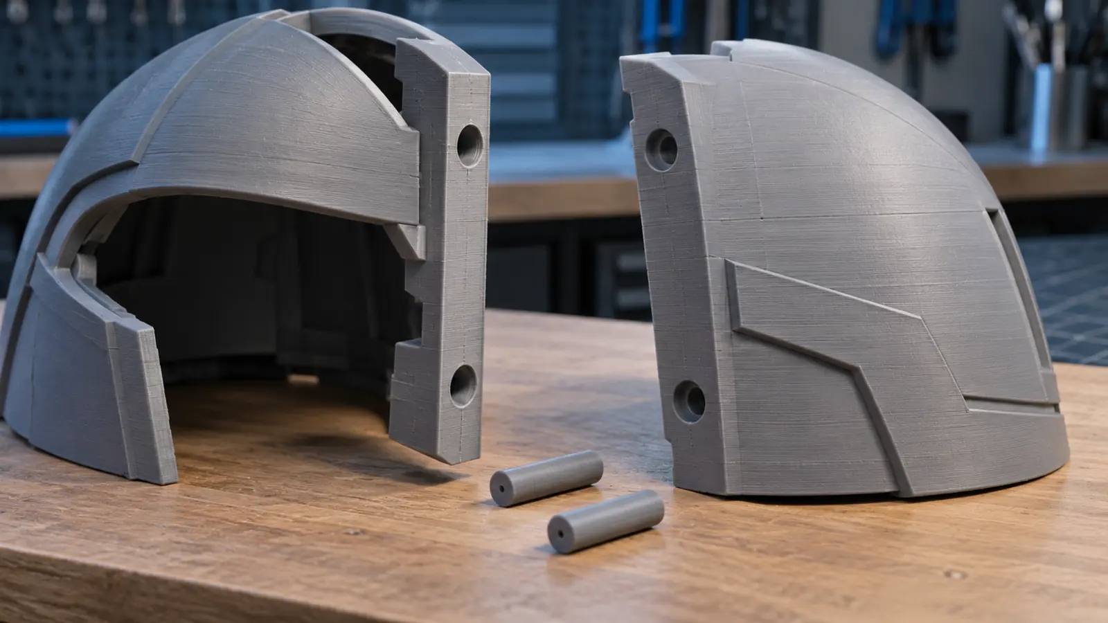
Planning example: decide before a long helmet print
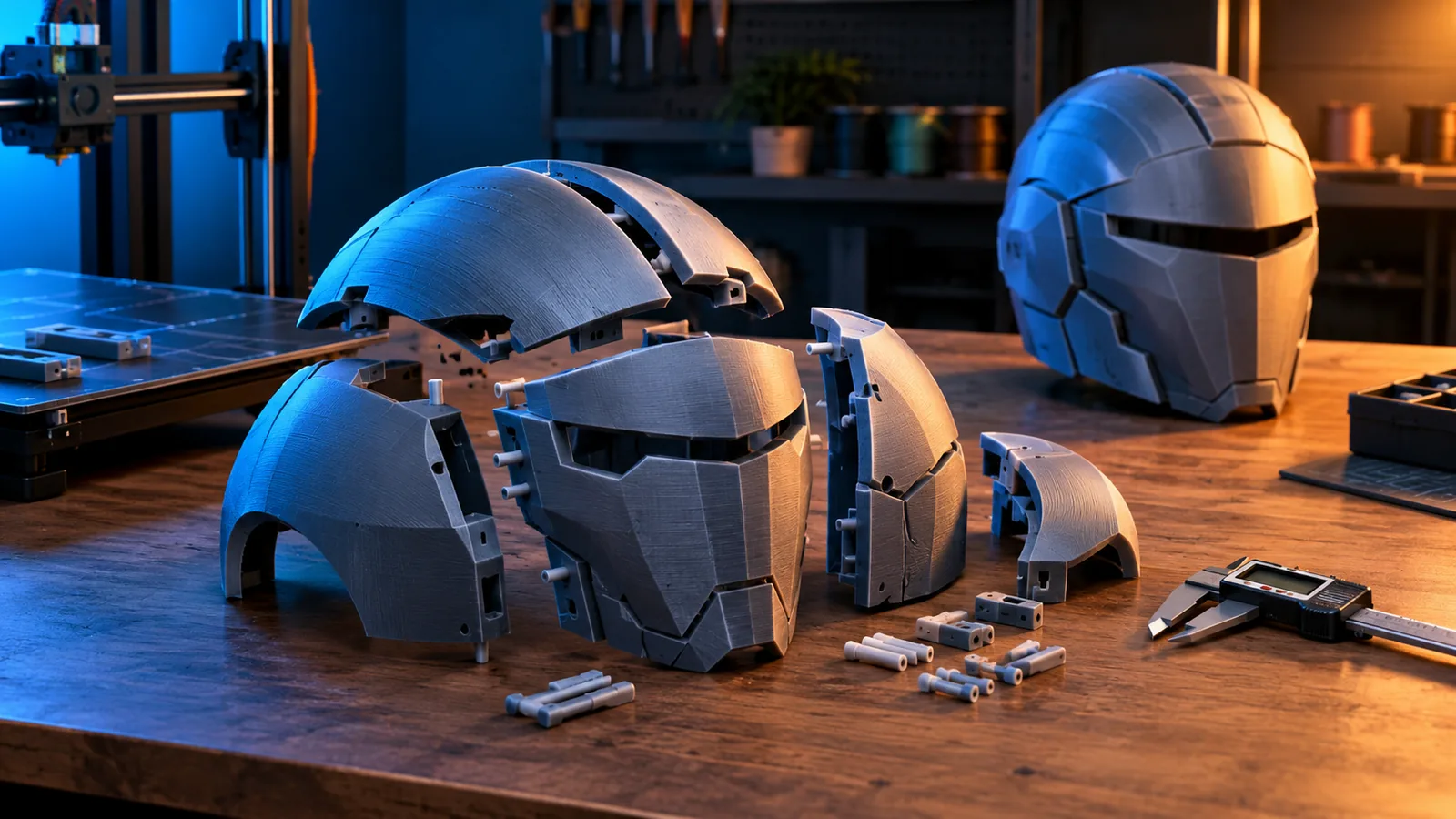
Illustrative workflow, not a documented print test: A helmet at final size exceeds the bed. Check another orientation first. If splitting remains necessary, choose segment count from build volume, seam position, support needs and assembly access rather than a universal number.
| Check | Decision before printing |
|---|---|
| Final size | Check internal clearance and opening; keep the same final scale across segments. |
| Cut | Prioritize stable support and enough connector-wall thickness over hiding every seam. |
| Connector | Test a local fit first. Separate dowels allow replacing a pin without reprinting both large segments. |
| Build volume | Account for brim, supports and clearance in the actual print orientation. |
| Assembly | Make sure pins can be inserted and bonding faces remain accessible. |
Prusa describes Dowel as separate pins with pockets in both parts. Details depend on the slicer. Inspect generated objects and dimensions rather than selecting solely by connector name.
- Set final size and check the internal contour.
- Plan cuts and connectors; check the bed including auxiliary structures.
- Print a section of the actual joint in the intended orientation.
- If it fits, print the large sections, cool them and bring them together without glue.
- Insert individually checked connectors; glue or close mechanically only after a complete dry fit.
A successful coupon verifies local fit, not the flatness of a full-size segment. Large faces can still warp. If assembly fails, first inspect the seam without connectors using the fit troubleshooting guide. For removable panels, the magnet guide explains additional retention options.
When should you split in CAD instead of the slicer?
Modern slicers are fast for simple planar cuts. CAD or mesh editing is better when:
- the split has to follow a complex contour,
- you need custom screw bosses or reinforcement,
- magnet pockets need exact dimensions,
- interlocking or functional joints are required,
- wall thickness around connectors must be redesigned.
The slicer is excellent for fast, reversible segmentation. CAD remains the cleaner level for actual construction changes.
Checklist before the long print
| Check | Question |
|---|---|
| Scale | Is the final target size fixed and identical for all sections? |
| Build volume | Does each section fit with room for brim/support and machine margins? |
| Cut | Is the seam sensible for both printing and finishing? |
| Connector | Is there enough material around the pin, slot or pocket? |
| Clearance | Was the fit tested using the real material and profile? |
| Orientation | Are visible and mating surfaces kept away from support where possible? |
| Warping | Could a long section distort the mating face while cooling? |
| Assembly | Can you perform a complete dry fit before bonding? |
Conclusion
Large 3D printed models are most reliable when scaling, splitting and joining are treated as one workflow. Final size comes first. Cuts are then placed so printability, seam visibility and assembly all work together.
Connectors make alignment easier, but useful clearance does not come from one universal table. A small test coupon and a complete dry fit can save far more time than they cost on helmets, armor and large figures.
Sources & current status
- Prusa Knowledge Base – Cut Tool, dovetail and connectors
- Bambu Lab Wiki – Cut Tool
- Bambu Lab Wiki – splitting large files and adding connectors
- Formlabs – printing models larger than the build volume
- BigRep – oversized parts: segmentation, orientation and assembly
Research status: October 9, 2026. Slicer features and connector types may change between versions. Connector clearance depends on printer, material and profile and should be validated with a small test part.
Frequently asked questions
Should I scale a large model before or after splitting it?
Scale it to the final target size first and split afterwards. This keeps every section and connector geometrically consistent.
What connector clearance should I use for 3D printed parts?
There is no universal value. Printer, material, flow, XY compensation and orientation all affect real fit. A small stepped test coupon is more reliable.
How should I split a helmet for 3D printing?
Use existing design lines where practical, favor printable base surfaces and place connectors only where enough wall thickness exists. Final helmet size should be set before splitting.
Can I scale split sections separately?
Avoid it for mating sections. Independent scaling changes the cut surfaces and quickly creates offsets and uneven seams.
When should I split a model in CAD instead of a slicer?
Use CAD when the cut must follow complex contours or when you need designed screw bosses, reinforcement, magnet pockets or functional joints.