Magnets can create removable joints for covers, enclosures and split models. Choosing glue, press fit or mid-print embedding depends on more than appearance: fit, polarity, temperature and future access all matter.
For a first attempt, an accessible pocket with a tested adhesive fit is usually easier to inspect than a fully enclosed magnet. Press fitting needs a fit test; mid-print insertion additionally needs a proven pause and secure retention.
1. Choose the method for the part
| Method | Useful when … | Check first |
|---|---|---|
| Glue after printing | the pocket remains accessible and polarity can be checked before curing | adhesive compatibility, bond gap and complete cure |
| Press fit | a tested pocket mechanically retains the magnet | dimensions, pocket walls, print orientation and brittle coating |
| Insert during printing | the magnet should be invisible and permanently enclosed | pause, retention, tool clearance, temperature and roof layers |
| Mechanical cover | the magnet should remain replaceable | escape prevention, screw/snap connection and access |
Here, magnets retain a removable joint. Pins or stops often work better for aligning segments. Combine them with the large-model scaling and splitting workflow rather than hiding poor alignment behind stronger magnets.
2. Measure the magnet and test a pocket coupon
Measure several magnets from the actual batch. Record diameter or width, thickness and pole orientation. CAD pocket dimensions are not automatically printed dimensions: material, flow, orientation and the first layer affect fit.
Illustrative example, not a measured test: For a disc measured at 6.00 mm diameter and 3.00 mm thickness, print a small coupon with 6.00 / 6.10 / 6.20 / 6.30 mm pocket diameters. These are test increments, not universal recommended clearances. Adding 0.20 mm to diameter provides 0.10 mm per side.
Use the final part’s material, profile and pocket orientation. After cooling, check insertion without force, the required adhesive gap and clearance below the closing surface. Add a side removal opening to the coupon so test magnets do not remain trapped.
Test depth separately from diameter. Adhesive under the magnet needs room and can lift it. An embedded magnet, including adhesive or retention features, must remain clear of the next toolpath. For general fit problems, see split printed parts that do not fit.
3. Glue after printing: check polarity before curing
An open pocket makes inspection and replacement easier. Remove loose debris, dry-fit the magnet and choose an adhesive whose data sheet covers both printed polymer and magnet coating. Epoxy and cyanoacrylate are candidates, not guaranteed solutions for every combination.
Prepare surfaces according to adhesive and magnet instructions. Avoid uncontrolled coating damage and check solvent compatibility before touching the printed part. K&J Magnetics advises against hot glue on neodymium magnets because of heat exposure.
Check the mating part before fixing the magnet. The cover and counterpart need attracting orientations. Allow a full specified cure before magnetic attraction loads the joint, and prevent newly glued magnets from pulling each other out.
4. Press fit: test retention instead of forcing insertion
A snug pocket can work without adhesive when verified in the actual printed part. The coupon decides, not nominal CAD diameter. An entry chamfer assists alignment; sufficient surrounding material helps prevent a thin wall from splitting.
Insert straight with controlled pressure, without hammering. Neodymium magnets and coatings can be damaged under excessive stress. Cracking, chipping or visible distortion means the fit is unsuitable. Printed polymers can change under sustained load, so recheck retention after repeated opening.
5. Insert during printing: workflow and pause placement
Use this method only after a small trial. The pocket must remain accessible for insertion and then be closed by subsequent layers. The trial must show reliable retention and a successful roof.
- Slice the part and locate the first toolpath closing the pocket. Pause before it, once the pocket is complete but still open.
- PrusaSlicer documents Insert pause print on the layer slider; it pauses before the selected layer. Its documented Prusa command M601 is not a universal command for Klipper or other firmware. Use the printer profile’s supported pause and test parking, temperature handling and resumption.
- Mark polarity using a reference magnet and verify against the mating part. Insert with the head parked, without moving the part or bed.
- Secure the magnet with tested mechanical retention or an adhesive suitable for that surface and temperature. A loose magnet can be attracted to steel parts of the print head. Do not resume with unsuitable or insufficiently cured adhesive.
- Check height and tool clearance, resume and watch the first covering paths. Stop if the magnet lifts or a collision is possible.
The first roof layer must span the actual cavity. Inspect its bridge and supports in the slicer. Roof thickness depends on loading and printability; plastic between the magnet and counterpart also increases separation. Test the completed assembly, not just two loose magnets.
6. Consider temperature, polarity and holding force together
Magnet grade alone is not a thermal approval. Check the specific magnet, geometry and service conditions. Maximum operating temperature differs from Curie temperature; permanent loss of magnetization can occur below the latter.
Nozzle temperature alone cannot establish the inserted magnet’s temperature. Bed, chamber, conduction and exposure duration all matter. When thermal exposure is unknown, insertion after the print cools is easier to control.
Use a marked reference magnet for a batch and check each mating part before permanent closure. Effective retention depends on separation, counterpart, alignment and loading direction. A supplier’s pull rating against steel does not guarantee performance in a plastic lid.
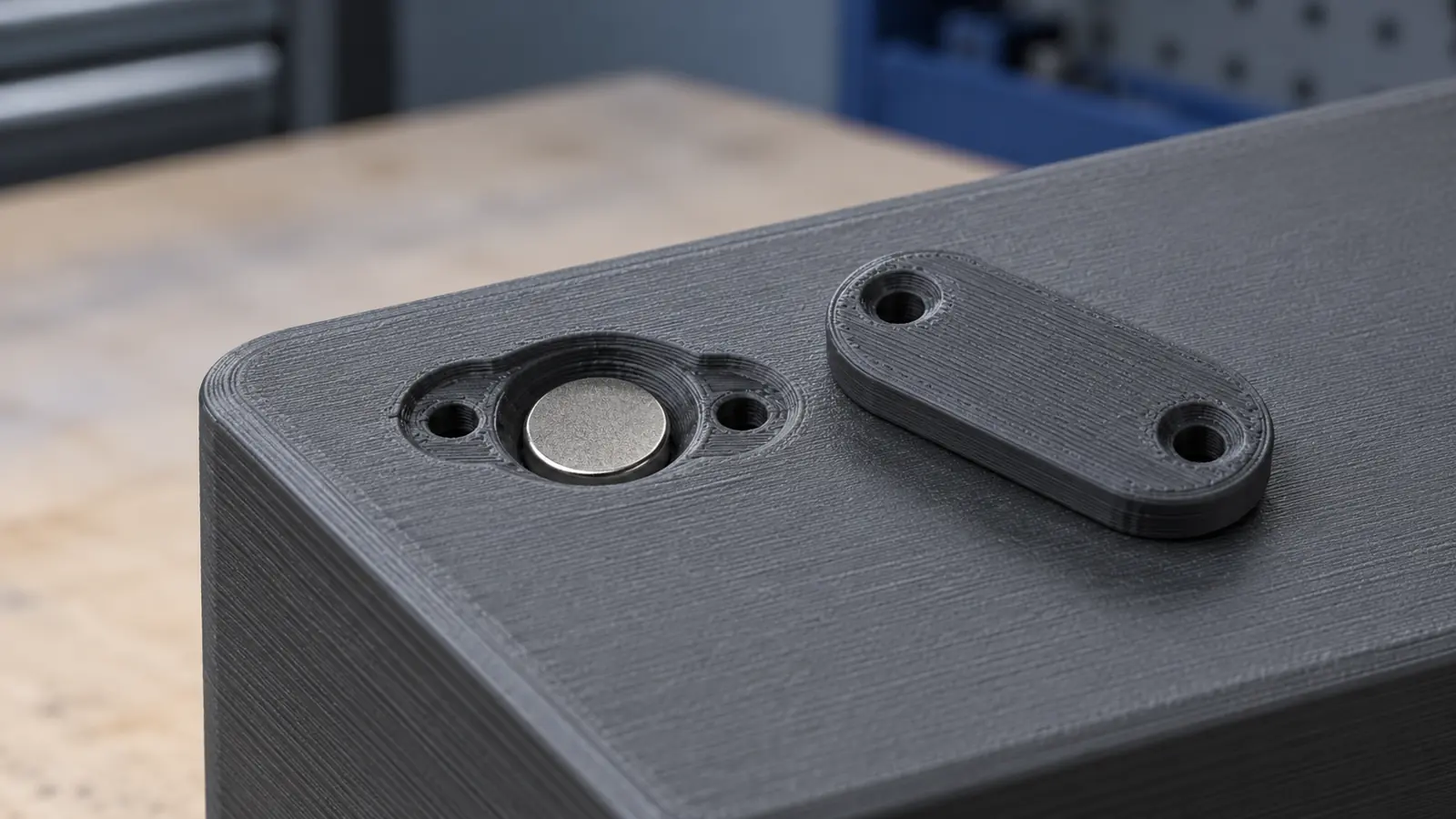
Mechanical closure: when access matters
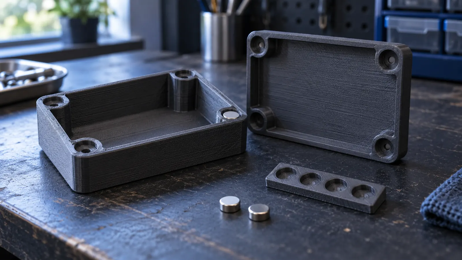
For a replaceable magnet, design a separate cover instead of printing it permanently inside the part. The cover retains the magnet in its pocket; attraction to the counterpart is a separate function. Screws or snaps need adequate supporting material and must not intrude into the magnet pocket.
| Decision | Check before closing |
|---|---|
| Maintain access | Can the cover be removed without destroying the main part? |
| Control height | Does the magnet fit beneath the cover without lifting it? |
| Check load path | Is magnet pull transmitted through adequately supported features? |
| Account for separation | Is retention adequate with the actual plastic layer in between? |
Test the closed pocket in the intended assembly. A snug individual magnet does not prove that screw locations, cover and counterpart survive repeated loading. The image illustrates an assembly idea, not a tested or dimensionally reproducible construction.
7. Accept the finished assembly
Test repeated opening and closing, sideways motion, individual magnet retention and part alignment. Record magnet specification, pocket dimensions, print profile, mounting method and completed checks. Accept the design only when it works in the intended assembly and no magnet becomes loose.
Small loose magnets must not remain accessible in products for children or pets. Friction alone or an unverified adhesive joint is insufficient protection for that use. A mechanically closed pocket can provide access for future replacement.
Sources and current status
- Prusa: pause at layer
- Prusa: embedding parts and magnets
- K&J Magnetics: adhesives
- K&J Magnetics: temperature
Research date: October 13, 2026. The coupon example is illustrative, not a report of our own measurements. Check firmware, adhesive and magnet specifications for the actual setup. The article image is an AI-generated illustration.
Frequently asked questions
What clearance does a magnet pocket need?
There is no universal value. Measure the batch and test pockets with the final profile and orientation.
Which layer should contain the pause?
Before the first path covering the completed, still-open pocket. Check the preview and actual printer pause behavior.
Can I insert a loose magnet?
No. Secure it below the next toolpath so it cannot lift or be struck.