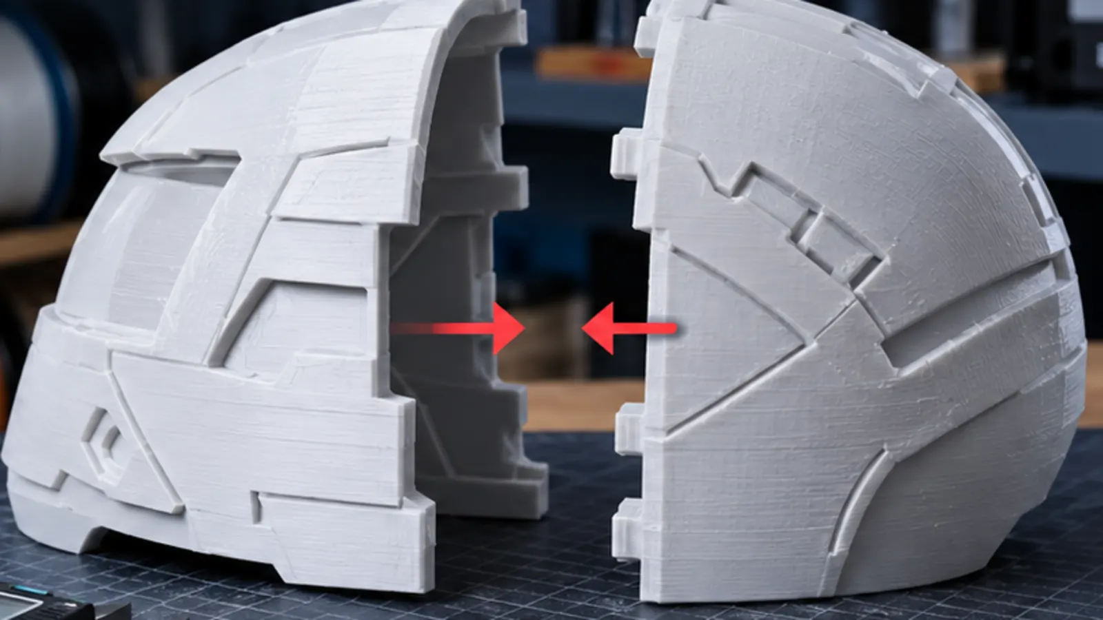
Everything looks perfect in the slicer: you cut a helmet, large figure or enclosure into multiple parts, the cut faces line up exactly, and pins or connectors appear to fit. After printing, however, a gap appears, edges collide, a pin will not enter its hole, or two large sections only close when forced together.
That does not automatically mean the slicer cut was wrong. Between mathematically perfect geometry and a real FDM print sit first-layer compression, extrusion, shrinkage, warping, print orientation and manufacturing tolerance. On large parts such as helmets, very small dimensional errors can accumulate over long distances and become obvious at the joint.
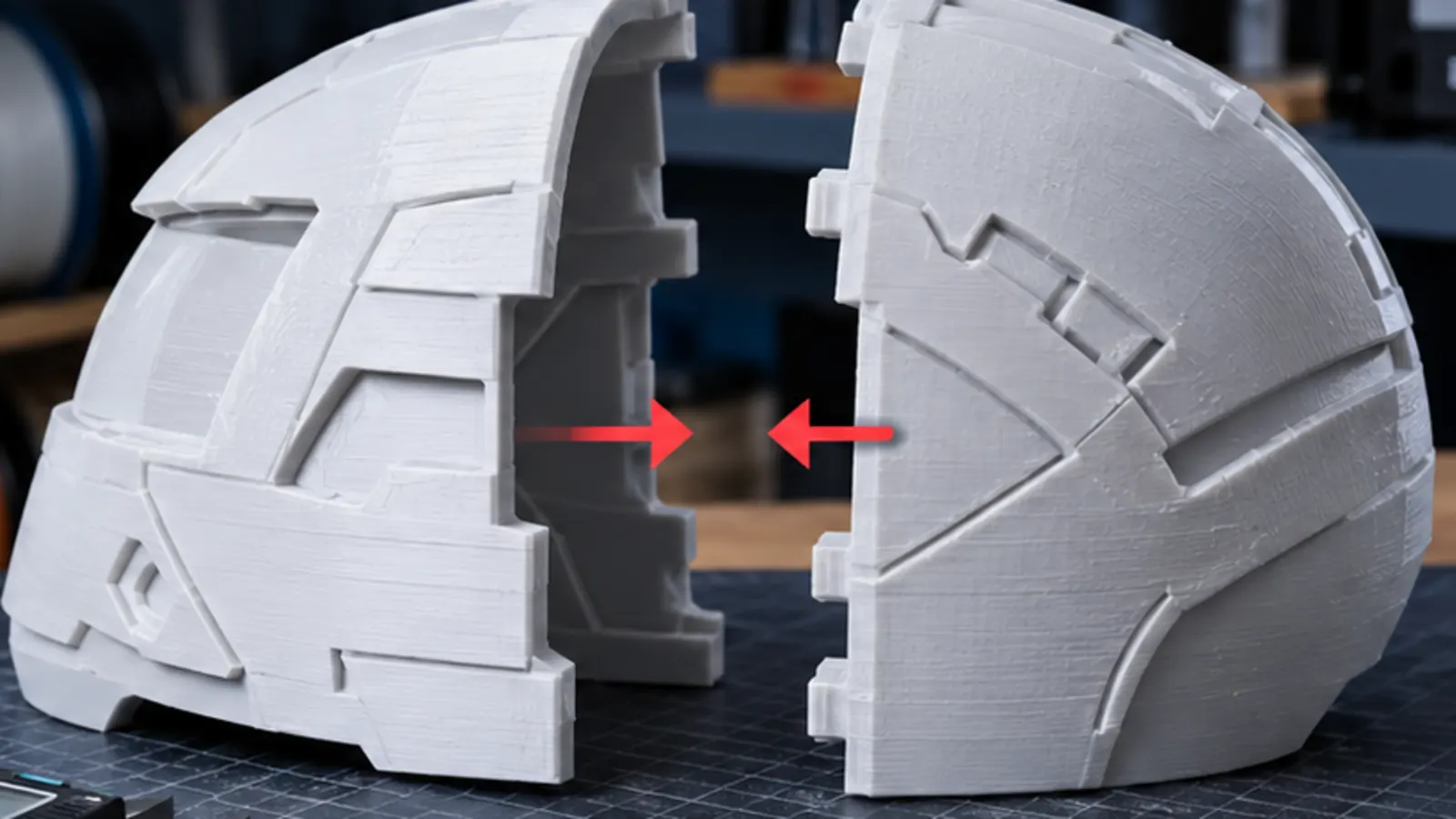
Why parts fit in the slicer but not in the real print
The slicer works with ideal geometry. A planar cut face is perfectly flat, a 6 mm pin can be exactly 6.00 mm, and its matching hole can also be 6.00 mm. The printer cannot reproduce that geometry without process effects. Plastic is extruded hot, pressed against the bed, cooled and sometimes distorted differently depending on material and geometry.
| Error type | Typical symptom | Likely direction |
|---|---|---|
| local error | only at the bottom, one corner or a support face | elephant foot, warping, support, seam |
| constant dimensional error | joint is similarly wrong along most of its length | flow, XY compensation, shrinkage, calibration |
| fit error | pin will not insert, hole is undersized, slot is too tight | missing clearance, hole/contour compensation, elephant foot |
| shape error | parts are bowed or twisted against one another | warping, orientation, temperature/cooling |
1. Diagnose elephant foot: bottom edge or the whole fit?
Elephant foot is an enlarged contour near the bottom of a print. On a bed-facing joint, this local lip can stop otherwise matching parts from fitting. Inspect cooled parts: does only the bottom edge bind, or does the whole height? A globally oversized contour can also involve CAD clearance, scaling or other dimensional errors.
| Observation | Check next | Poor shortcut |
|---|---|---|
| Only the bed-facing edge binds | Inspect the first layer separately from the contour above. | Scale down the entire part. |
| First-layer paths are ridged, displaced or scraped | Check Z reference and plate profile using the device procedure; stop scraping. | Keep printing with large contour compensation. |
| Several lower layers widen; higher contour is plausible | Inspect thermal conditions and the actual affected height. | Copy a universal first-layer correction. |
| Fit is tight throughout its height | Check design clearance, internal/external dimensions and material process. | Treat every dimensional error as elephant foot. |
Check order: establish a stable first layer and reference. Evaluate bed/nozzle conditions within material and plate guidance. Print a small section of the real joint with unchanged orientation. Only then address remaining local widening with modest elephant-foot compensation or a design chamfer.
Slicers differ: PrusaSlicer describes adaptive first-layer correction; OrcaSlicer also provides a compensated-layer count. Inspect preview, thin features and brim attachment after each change. Aim for a fitting bottom edge with reliable adhesion, not the smallest possible footprint.
Accept the comparison: the cooled bottom edge fits without force, the remaining contour still fits, and adhesion/thin detail do not deteriorate. If lower paths are damaged or the coupon detaches, return to process checks. A chamfer changes design and must not remove required contact surfaces. Section checked October 13, 2026.
2. Wrong flow can hurt fit — but it is not a universal dimensional control
Excess material can build up outer contours, close small gaps and tighten connectors. A plausible Flow Ratio is therefore part of any dimensional-accuracy workflow. But it is also a mistake to correct every fit problem with flow.
If a 100 mm part shrinks proportionally or holes behave differently from outer contours, Shrinkage and X-Y Hole/Contour Compensation are the more appropriate tools. OrcaSlicer explicitly separates these corrections and includes a tolerance test for the specific printer/filament combination.
For the calibration order see Filament Calibration in OrcaSlicer.
3. Material shrinkage: small percentages become visible on large helmet sections
Plastic shrinks as it cools. The real effect depends on material, part geometry, thermal conditions and printer. OrcaSlicer therefore provides separate shrinkage compensation for XY and Z. This matters on large parts: a small percentage that is barely noticeable on a 20 mm test piece can create a visible mismatch across 200 or 300 mm.
Do not derive shrinkage from one tiny measurement. Use larger reference dimensions and repeat the test. If X and Y differ substantially, also investigate mechanics, skew and warping.
Our Dimensional Accuracy & Shrinkage Calculator helps distinguish proportional shrinkage from local hole/contour errors.
4. Warping: the cut face is no longer truly flat
A large helmet segment can be dimensionally close and still refuse to fit its neighbor. Even mild warping can twist or bow the mating face. The two pieces may touch at the top but leave a gap at the bottom — or the reverse.
- The gap grows toward one corner.
- The part rocks on a genuinely flat reference surface.
- The seam closes under hand pressure and springs open again.
- The section looks slightly banana-shaped or twisted.
More XY compensation will not fix that. Check bed adhesion, print orientation, material temperature, enclosure/ambient conditions and whether both sections were printed under comparable conditions.
5. Different orientations can distort matching faces differently
If one part is printed with the mating face on the bed and the other upright, the two surfaces experience very different process conditions. One sees first-layer compression; the other may show Z stepping or support contact. Shrinkage and internal stress can also act differently.
For large matching sections, plan orientation deliberately. The pieces do not have to be printed identically, but you should know what each orientation does to the critical interface.
6. Supported faces are rarely perfect mating faces
A surface that is planar in the slicer can become rough, slightly wavy or locally depressed after support contact. On a visible glue seam, one raised spot can hold the entire opposite part away.
- orient critical mating faces without support when practical,
- tune support Z distance and interface properly,
- inspect for isolated high points after support removal,
- for glued joints, flatten carefully instead of aggressively sanding away geometry.
7. Seams, blobs and local overextrusion can mimic a dimensional error
A single Z seam placed on the mating face can hold two otherwise correct parts apart. The same applies to blobs, stringing remnants or support scars.
Before rescaling the model, hold the parts together against a light and identify where they make contact first. The true interference point is often much more local than the visible gap suggests.
8. Pins, dowels and connectors need deliberate clearance
A 6.00 mm pin inside a 6.00 mm hole is geometrically aligned in CAD, but it is not a robust real-world FDM slip fit. Printer, filament and geometry need intentional clearance.
OrcaSlicer includes a tolerance test with several steps from 0.0 to 0.4 mm. Those values are not universal recommendations; the test demonstrates the correct principle: fit clearance should be tested for the actual printer/filament combination.
Also treat outside contours and holes separately. OrcaSlicer provides distinct X-Y Hole Compensation and X-Y Contour Compensation for exactly that reason.
9. Why “just scale everything to 100.5%” is often the wrong fix
Global scaling changes everything at once: outside dimensions, holes, wall thickness, pin spacing and the overall shape. If only a hole is undersized or only the first layer is too wide, scaling can make other areas worse.
Scaling makes sense when you have actually measured a reproducible proportional dimensional error. For local fit problems, design clearance, hole/contour compensation or elephant-foot compensation are more targeted.
10. Fast diagnostic workflow
| What you see | Check first |
|---|---|
| joint gap is similar everywhere | global dimensional accuracy, shrinkage, flow/calibration |
| only the bottom binds | elephant foot, first layer, chamfer |
| gap grows toward a corner | warping / twisted mating face |
| only pins or holes fail | design clearance, hole/contour compensation |
| only supported side fits badly | support contact, cleanup, orientation |
| one tiny spot holds the entire seam open | seam, blob, support remnant, burr |
| parts from separate print jobs behave differently | profile, filament condition, temperature, printer state |

11. Use a fit coupon that separates the actual problem
First bring fully cooled segments together without removable pins. Do not force integral connectors together: they can hide the contact between faces. Check an actual joint section or a separate variant first.
| Observation | What the next test distinguishes |
|---|---|
| Faces meet correctly without pins | Test every pin in each pocket separately: diameter, depth and pairing. |
| Pin fits but seam remains open | Check pocket depth and pin length; the pin may bottom out. |
| Seam closes only under force | Check flatness and warping instead of increasing pin clearance. |
| Only the pocket entrance binds | Inspect lower edges, chamfers, burrs and first layers. |
Take a small section of the real connection. Preserve wall thickness, orientation, layer height, material and profile. An unrelated hole printed in another orientation can behave differently. Orca’s documented tolerance test helps establish a baseline; it does not automatically verify a different connector geometry.
- Print an unchanged first coupon and let it cool completely.
- Check pin and pocket separately and record the interference location.
- Change only the relevant dimension: clearance, depth or a local lower edge.
- Reprint with the same profile; do not also alter flow and global scale.
- Record the successful configuration before reprinting large segments.
Calculation example: A 6.00 mm pin and 6.20 mm pocket have a geometric diameter difference of 0.20 mm, or 0.10 mm per side. This is not a print recommendation. Check whether a slicer field describes radius, diameter, percentage tolerance or a contour offset. Orca separates hole and outer-contour compensation; do not transfer the calculated clearance blindly into another setting.
12. A sensible fix order
- Verify the split geometry: are pins, slots and mating faces actually correct?
- Check the first layer: no excessive elephant foot.
- Calibrate filament: plausible temperature, Flow Ratio and Pressure Advance.
- Measure large references: do not judge X/Y/Z from a 20 mm cube alone.
- Test fits separately: holes and outside contours are different problems.
- Rule out warping: check mating-face flatness.
- Remove support/seam interference: find local high spots.
- Print a fit coupon: only then restart the large helmet or enclosure.
Conclusion
When split 3D printed parts do not fit after printing, the slicer cut is rarely the only explanation. More often, several small manufacturing effects combine: elephant foot, flow, shrinkage, warping, print orientation and insufficient design clearance.
The most useful step is to locate the error spatially. A uniform dimensional error needs a different correction from one lifted corner or one undersized pin hole. That prevents global scaling or random slicer changes from creating new problems.
If the symptom is still unclear, use the 3D Printing Troubleshooter and the Dimensional Accuracy & Shrinkage Calculator.
Sources & current status
- OrcaSlicer Wiki – Precision: X-Y Compensation & Elephant Foot Compensation
- OrcaSlicer Wiki – Filament Tolerance Calibration
- OrcaSlicer Wiki – Shrinkage (XY/Z)
- Prusa Knowledge Base – Elephant Foot Compensation
Research status: September 10, 2026. Required fit clearance always depends on printer, material, geometry and the intended joint.
Frequently asked questions
Why do parts that fit in the slicer fail to fit after printing?
The slicer shows ideal geometry. The real print can deviate because of elephant foot, flow, shrinkage, warping, support surfaces and insufficient fit clearance.
Should I scale the entire model up or down?
Only after proving a reproducible proportional dimensional error. Local hole, contour or first-layer problems should be corrected more selectively.
Why do a pin and hole with the same CAD dimension not fit?
A real FDM slip fit needs intentional clearance. Internal and external contours also respond differently to process error and slicer compensation.
Can excessive flow make split parts not fit?
Yes. Overextrusion can build up contours and tighten fits. Flow should be calibrated correctly rather than used as a substitute for shrinkage or XY compensation.
How can I test a helmet joint without reprinting the entire helmet?
Cut out a small section of the actual mating geometry and print it as a fit coupon. This tests clearance and material behavior with very little time and filament.