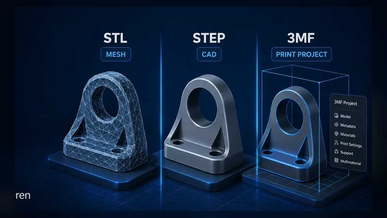
STL has been the default hobby 3D-printing format for decades. Modern slicers increasingly accept STEP and 3MF as well, which creates a common misconception: “STEP is automatically more accurate than STL.” The real difference is what information the file stores and when tessellation happens.
STL: a triangle mesh, not true CAD geometry
An STL stores the model surface as triangles. It does not know that a hole is mathematically circular or that two faces are tangent. If the export uses too few triangles, curved surfaces become faceted before the slicer ever sees the model.
Why a coarse STL can create visible facets
A high-resolution printer cannot restore geometry that was removed during export. If a 40 mm cylinder is approximated with a small number of large flat facets, the toolpath follows those facets. Reducing layer height does not fix a poor XY mesh.
STEP: CAD surfaces and solids are preserved
STEP can preserve analytic surfaces, edges and solid-body relationships from CAD. A modern slicer can tessellate those surfaces at import using its own tolerance. That gives the slicer better source geometry than a coarse STL.
Why STEP often looks cleaner after slicing
If the STL was exported with low resolution, STEP avoids that early loss of detail. The slicer creates its own mesh from the CAD surfaces and may produce smoother arcs and circles.
STEP is not infinitely accurate inside the slicer
The slicer still has to convert CAD geometry into toolpaths. Import tolerance, maximum deviation and path resolution remain relevant. STEP preserves better source geometry; it does not eliminate discretization.
3MF: more than a model format
3MF can package geometry together with units, object arrangement, colors, material assignments and print-project settings. That makes it particularly useful for sharing a complete slicer project or a multi-material setup.
STL, STEP and 3MF compared
| Format | Main strength | Main limitation |
|---|---|---|
| STL | Universal simple mesh exchange | Quality depends on export tessellation; little metadata |
| STEP | Mechanical CAD geometry | Not a complete slicer project |
| 3MF | Print project, multiple parts and metadata | Some settings remain slicer-specific |
When STL is still perfectly fine
A well-exported STL can be visually indistinguishable from STEP on a typical FDM print. Organic models from sculpting software are meshes anyway, so STEP adds little value there.
When STEP is the better choice
Mechanical parts with arcs, holes, fillets and CAD-derived geometry are strong candidates. It is also useful when the recipient may want to inspect or edit solid geometry.
When 3MF is the better choice
Use 3MF when you want to preserve the slicer project: orientation, multiple objects, color assignments, per-object modifiers or tool mappings. For toolchanger prints, that can save a lot of setup.
Example: a round hole in CAD
In CAD the hole can be a true cylinder. Exporting a coarse STL replaces the circle with a polygon. Exporting a fine STL approximates it with many more facets. STEP keeps the cylinder definition until the slicer tessellates it.
Can the printer reproduce the extra accuracy?
Not always. Nozzle diameter, line width, motion resolution and material shrinkage set practical limits. There is no benefit in generating a gigantic mesh far beyond what the printer can physically reproduce.
Which STL export settings matter?
Chord height/deviation and angular tolerance are more meaningful than a vague “high quality” preset. Use a tolerance fine enough that curves are smooth at the final part scale without producing unnecessarily huge files.
STEP is especially useful in reverse engineering
Scan-to-CAD workflows often end in editable CAD surfaces or solids. Preserving that geometry through STEP is useful when dimensions, holes and interfaces still need to be modified before printing.
3MF is not automatically a CAD replacement
3MF can carry rich print-project data, but it does not replace a parametric CAD source file. If the design must remain editable, keep the original CAD file as the design master.
What happens after import into the slicer?
Regardless of format, the slicer eventually generates discrete extrusion paths. The advantage of STEP is that the conversion begins from analytic CAD geometry; the advantage of 3MF is that the print context can travel with the model.
Why can STEP sometimes look worse?
If the slicer uses a coarse import tolerance or the CAD model itself contains problematic surfaces, STEP can still be tessellated poorly. File format does not fix bad source geometry or bad import settings.
Multi-part models and toolchangers
3MF is particularly convenient for assemblies, color-separated objects and tool assignments. It can preserve which body belongs to which material or extruder, while STL normally requires separate files and manual assignment.
What does LayerCompass recommend in 2026?
- Mechanical CAD: STEP as a strong source format, plus STL when broad compatibility matters.
- Sculpted/mesh models: high-quality STL or 3MF.
- Ready-to-print projects: 3MF.
- Editable design master: keep the original CAD file regardless of print export.
Which files should you publish?
For a technical model, offering STEP plus a well-exported STL gives users flexibility. Add 3MF when you want to provide a tested slicer/project setup. Avoid making a slicer-specific 3MF the only source when users may need to edit the design.
Conclusion: the best format depends on the workflow
STL is not obsolete, STEP is not magically “more printable,” and 3MF is not just another mesh file. Choose the format according to whether you need universal mesh exchange, preserved CAD geometry or a complete print project.
STL quality depends on export tessellation
An STL is not inherently low quality. A finely exported mesh can represent a smooth CAD surface extremely well. The problem is that STL stores only triangles, so the quality is fixed at export. If a cylinder was exported with too few facets, the slicer cannot reconstruct the original mathematical circle.
This is why two STL files of the same CAD model can produce very different surface quality and file size.
STEP keeps CAD geometry longer in the workflow
STEP can preserve analytic and parametric-style geometric definitions such as planes, cylinders and NURBS surfaces. A slicer that imports STEP still has to tessellate that geometry for toolpath generation, but the tessellation happens later and can use the slicer’s own resolution settings rather than a coarse mesh chosen by the model author.
3MF is often the best print-project format
3MF can package mesh geometry together with print-oriented information such as multiple objects, transformations, colors, material assignments and slicer project settings. That makes it ideal for sharing a print setup, whereas STEP is stronger as an exchange format for CAD geometry.
What each format does not guarantee
| Format | Strong at | Does not guarantee |
|---|---|---|
| STL | Universal simple mesh exchange | Units, materials, CAD editability, fine tessellation |
| STEP | CAD geometry exchange | Perfect slicer import, print settings, native feature history |
| 3MF | Modern print/project packaging | Editable parametric CAD source |
Mechanical parts: keep the CAD source
For parts you design yourself, the most important file is often neither STL nor 3MF: it is the original CAD document. Export STEP for geometry exchange and 3MF for the slicer project, but keep the native source if future dimensional edits matter.
Curved surfaces and visible faceting
If a round surface prints as obvious flat segments, inspect the model preview before blaming the printer. If the facets are already present in the mesh, smaller layer height or slower printing cannot remove them. Re-export at finer tessellation or use STEP when supported.
File size vs. geometric fidelity
Extremely dense STL meshes can become huge without improving the printed result because nozzle diameter, line width, machine resolution and slicer path simplification impose their own limits. The goal is sufficient geometric resolution, not the largest possible triangle count.
Recommended workflow
- Downloading a simple model: STL is still perfectly usable when the mesh quality is good.
- Sharing mechanical CAD geometry: prefer STEP.
- Sharing a prepared slicer project: prefer 3MF.
- Archiving your own design: keep the native CAD file plus an exchange format.